Contents:
- Introduction
- Product creation process.
- Requirements for models for 3D printing and CNC processing.
- Fixing non-fatal errors with NetFabb.
- Fixing non-fatal errors with MeshMixer.
- Fixing non-fatal bugs with Materialize Magic.
- Examples of the most common mistakes.
Introduction.
In this article, we will talk about the basic and general parameters that a model must meet in order to obtain high-quality 3D printed products. Let's discuss common mistakes that arise in the process of creating 3D models in terms of high-quality polygonal mesh and how to quickly fix them. Requirements for XNUMXD models and quality issues in terms of accuracy of manufactured parts are described in another article: Actual product size after 3D printing.
ATTENTION! This article is dedicated to designers, designers, 3D designers, 3D artists and professionals who work with 3D modeling programs. In case you are not such a specialist, you need to transfer this article to your specialist in working with 3D models or ask our studio for help in creating a 3D model. To do this, you need to draw up a technical task for 3D modeling and send it to our email address.
CONTACTS TERMS OF REFERENCE TEMPLATE
The process of creating a product.
The structure of the additive technological process for the production of products:
| Designer / 3Dartist | 3D printing service | Errors discussed |
| 1. Creating a 3D model | ||
| 2. Export / convert 3D model to the required format | 3. Checking the model for suitability | 4. Compliance / non-compliance with the minimum permissible thicknesses. |
| 6. Preparation of a control program for a 3D printer (GCode) | 5. Compliance / non-compliance with the requirements for the polygonal mesh of the 3D model. | |
| 7. 3D printing process. | ||
| 9. Quality control. | 8. Post-processing process. |
In accordance with the presented algorithm, at the first stage of product creation, a 3D model is developed using modeling programs in accordance with the terms of reference and the requirements of standards. After that, it is necessary to export the data of the program file of the simulation result in a format that is accepted by the program of the control machine of additive manufacturing (for example, "STL"). The modeling process can currently be performed not only in solid format, but also directly in STL. Before the next stage, possible defects of the model are identified. The model intended for 3D printing must be airtight, monolithic and not contain cavities and breaks in the walls, which is ensured using special programs. Next, the information from the STL file is converted into commands, following which the 3D printer produces the product, this is the so-called GCode.
During this procedure, you should select the desired scale of the part, the correct position in space, and also accurately position the model on the working surface. The result of the whole process, strength, surface roughness of the part and material consumption depends on this.... After making the settings, the model is divided into layers of material, "stacked" into the body of the part in one working cycle of the additive machine. This process is called slicing. Slicing is done using the software supplied with the machine or using special tools (Simplify, Skein-forge, Slic3r, KISSlicer, MakerWare, etc.). The G-code obtained at the previous stage is transferred to the 3D printer via a flash memory or via a USB cable. In the process of preparing and adjusting the additive machine, calibration, preheating of the working bodies, the choice of the model material and the setting of the parameters of the equipment operation modes depending on it are performed. On professional grade devices, this step can be combined with the slicing process. After all the preparatory operations have been completed, the printing process starts, that is, layer-by-layer combining of materials. Its duration depends on the type of technology and the selected parameters of accuracy and quality of part manufacturing.
Requirements for models for 3D printing and CNC processing.
- List of file formats for 3D technologies.
- FDM (ABS, PLA plastics, FLEX, HIPS, etc.): .STL .OBJ
- SLS (polyamide): .STL .OBJ
- SLA, DLP (photopolymer): .STL .OBJ
- SLM (metal): .STL + STP (STEP) .OBJ + STP (STEP)
- Multicolor plaster: .OBJ + Texture Unfold .WRL + Texture Unfold
- Polygonal mesh.
- The polygonal mesh must be uniform and closed. A model consisting of several polygonal meshes is not allowed! The intersection of polygonal meshes is not allowed! Holes in the net are not allowed!
- Multiple models in one file are not allowed. Each object needs to be saved in a separate file.
- The number of polygons must not exceed 500.
- The wall thickness must be at least set values for every technology.
- Inverted normals are not allowed! The outer normal must point outward. This problem occurs especially often when mirroring a model in some XNUMXD modeling programs.
- The dimensions of the model must correspond to the dimensions of the real object.
In 95% of cases, errors in files are not critical and they can be easily corrected in specialized programs that can be easily found on the Internet. Even if you are sure that everything is in order with the model, it does not hurt to check it again for correctness.
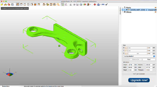
NETFABB - as a solution to most of the file errors.
MESHMIXER is a powerful and convenient alternative.
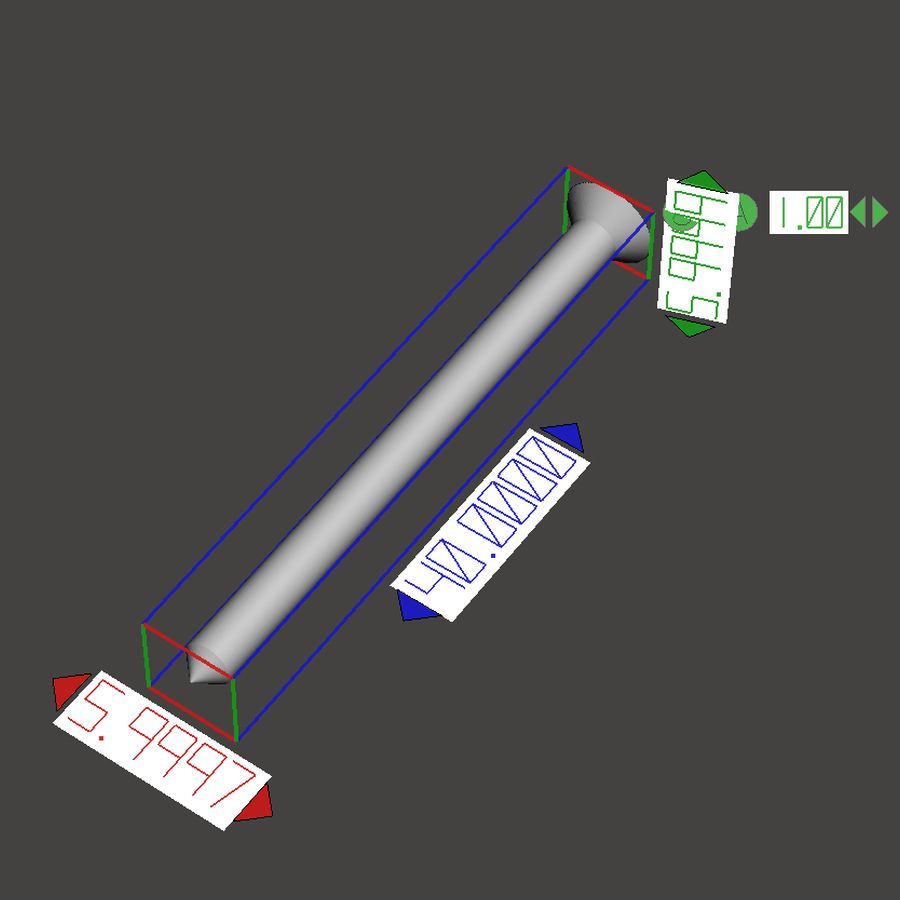
- Analysis of the wall thickness of the model.
It should be understood that there are several 3D printing technologies. They differ not only in the materials used, but also in the accuracy of the equipment. Different equipment has its own resolution. Therefore, before sending a file for printing, it is necessary to verify the quality of the model in terms of the specified thicknesses in walls, rods, and mesh floors.
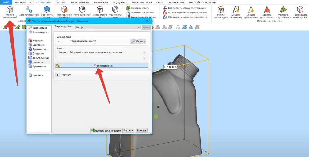
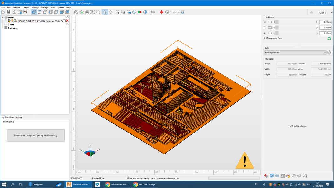
Correcting non-fatal errors with NetFabb.
NETFABB (download for PC or download for mac) Is a program that allows you to solve almost any issue related to 3D printing. Let's go through the main functions of this software, which was bought by AutoDesk itself.
The program shows the outer part of the polygon in green, and its inner normal in red. Ideally, the model should be all green. If you see red spots, then these are polygons that are turned outward. If the entire model is highlighted in red, then the entire polygonal mesh is turned outward.
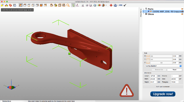
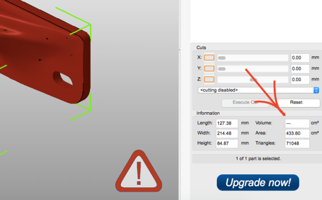
Even if the model is green, but there are errors in your file, the program will display a large exclamation mark in the lower right corner of the screen, and it will also not be able to calculate the volume of your model.
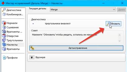
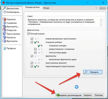
To treat the model, click on the red cross on the toolbar at the top of the screen. The program will switch you to the treatment mode, and in yellow it will indicate the breaks in the polygonal mesh, if any.
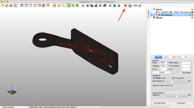
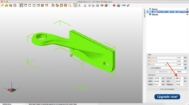
This program has functions for deleting or adding polygons, changing sizes or proportions. (I will leave these functions for independent study). I recommend that you study the entire toolbar in order to easily understand how, where and which polygons we can select and what we can change.![]()
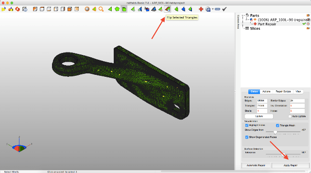
To invert the normals, select the polygons that look “in the wrong direction” and click on the “invert normals” button. Then click on the “Apply Repair” button.
If your model was initially all green or inverting the normals did not remove the exclamation mark, and the volume has not yet been calculated, you need to apply automatic treatment. To do this, go back to the treatment mode by clicking on the red plus. In the treatment mode, select "Automatic treatment", then select "Default Repair" and press "Exstrude".
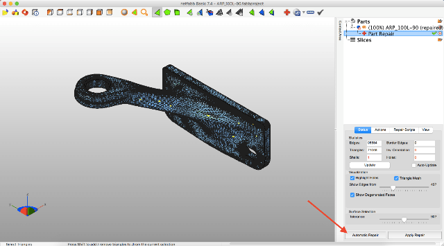
Now the program has done everything it can to automatically repair the model. Click “Apply Repair”.
Typically, these steps should have repaired your model. If, after the operations performed, an exclamation mark is burning for you and there is still no volume, then you are among those 5% when the model has critical errors and errors were incorporated even at the modeling stage.
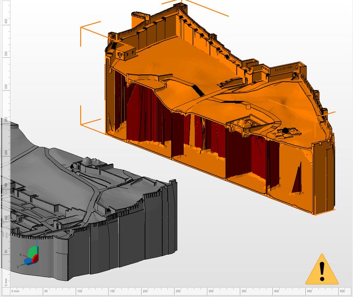
Correcting non-fatal errors with MeshMixer.
Autodesk MeshMixer - it free software for working with three-dimensional mesh models. You can download the program here to register:... The program does not have tools for creating 3D models, but there is a wide range of tools for modifying them and preparing them for XNUMXD printing. The main difference between this software and NETFABB is that MESHMIXER officially supports the latest versions of macOS. This is a decisive factor for me, because I always carry a MacBook with me, and a Windows computer is only in the office. In turn, NetFabb discontinued support for macOS software.
As with Netfabb, you need to drop the STL model into the MeshMixer window.

At first glance, the model looks good, but let's try to test it for suitability for 3D printing (for compliance polygon mesh requirements). To do this, you need to analyze the model for errors. To do this, go to the "Analisis" section, then click on the "Inspector" button.

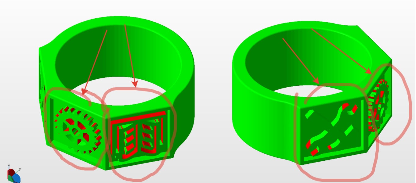
On the screen, we see how the program highlighted areas on the model with bright colors that do not meet the requirements, and therefore have errors.
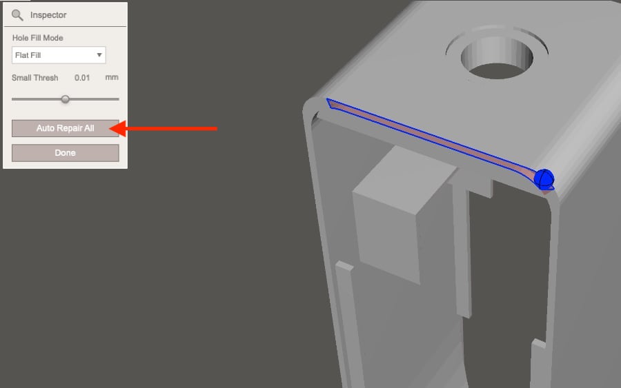
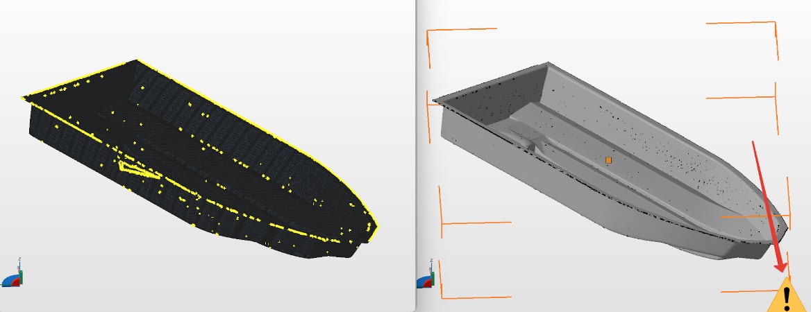
In order to fix (cure) these errors, click on the “Auto Repair All” button. The program will try to remove errors in automatic mode. Checking before 3D printing is mandatory. Even if outwardly the model seems suitable to you, it is still worth checking. In the picture below you can see the errors that are inside the polygonal mesh, although externally everything is fine with the model.

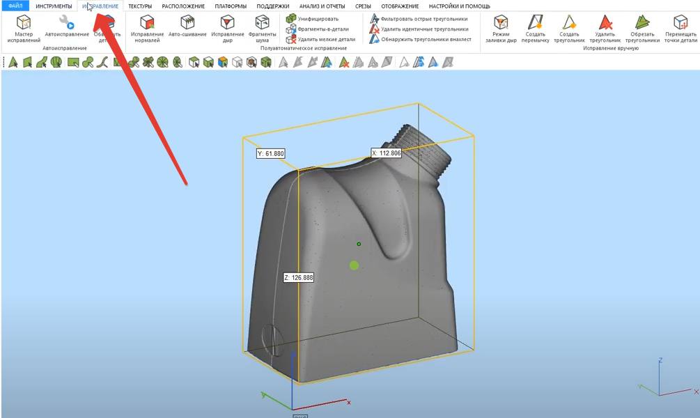
However, this treatment does not always help. For example, if there are a lot of errors in the model that the program is not able to remove automatically, then you will have to correct the model yourself in the program where the model was originally created. In case of a large number of errors, the program will indicate their presence even after you have tried to do automatic treatment. The picture below is an example of a very large number of shortcomings and errors that the program is not able to remove itself.

This happens, as a rule, when the model was prepared for rendering, and not 3D printing. That is, there are a huge number of surfaces, but they are not connected into a single mesh.
Fixing non-fatal bugs with Materialize Magic
The function of treating a 3D model in Materialize Magic is located in the "Fix" tab.
After that, you need to select the "Fix Wizard" command. Next, you need to alternate between the "Update" and "Autocorrection" buttons.
You need to do this several times. Sometimes it takes a long time. Until the moment when the number of errors becomes minimal or disappears altogether.
After the upgrade, the result below can be considered successful. All checkboxes should be green.
Complete the treatment by following the recommendations and save the corrected model!
A very important point! Treatment in automatic mode is based on the principle of adding or removing polygons. Therefore, after the automatic treatment, completely check the model for the correct shape. Suddenly the program deleted something or added something superfluous.
At the end, it is imperative to check the final model for wall thickness... All programs described in this article support this feature.
May the video card help you in studying three-dimensional modeling programs. =)
Examples of the most common mistakes.
Too thin walls in the 3D model on the extruded parts.

Many areas with a thickness of less than 1 mm

Inverted polygons, infinitely thin walls

Error converting to STL format, low polygonality

Inverted polygons, infinitely thin walls
Inverted polygons, overlapping polygons
Excess trash from landfills
Poor quality 3D scanning without processing the result


Author: Studia3D. Ru
More articles from Studia3D. Ru