FEDERAL AGENCY
FOR TECHNICAL REGULATION AND METROLOGY
GOSTR 57558— 2017 / ISO / ASTM 52900: 2015
ADDITIVE TECHNOLOGICAL PROCESSES.
BASIC PRINCIPLES
Part 1
Terms and definitions
(ISO / ASTM 52900: 2015, Additive manufacturing.
general principles. Terminology, IDT)
Official edition
2017
foreword
- PREPARED by the Federal State Unitary Enterprise "All-Russian Research Institute of Aviation Materials" (FSUE "8IAM") on the basis of its own translation into Russian of the English version of the standard specified in clause 4
- INTRODUCED by the Technical Committee for Standardization TC 182 "Additive Technologies"
- APPROVED AND PUT INTO EFFECT by the Order of the Federal Agency for Technical Regulation and Metrology of July 27, 2017 No. 752-st
- This standard is identical to the international standard ISO / ASTM 52900: 2015 “Additive manufacturing. Basic principles. Terminology "(ISO / ASTM 52900: 2015" Additive manufacturing - General principles - Terminology ". IDT).
The name of this standard has been changed relative to the name of the specified international standard for linking with the names adopted in the existing set of national standards of the Russian Federation
- INTRODUCED FOR THE FIRST TIME
The rules for the application of this standard are established in Article 26 of the Federal Law of June 29, 2015 "R 162-FZ "On Standardization in the Russian Federation". Information about changes to this standard is published in the annual (as of January 1 of the current year) information index "National Standards". and the official text of the changes and amendments is in the monthly information index "National Standards". In case of revision (replacement) or cancellation of this standard, a corresponding notice will be published in the next issue of the monthly information index "National Standards". Relevant information, notification and texts are also posted in the public information system - on the official website of the Federal Agency for Technical Regulation and Metrology on the Internet.
© Standartinform. 2017
This standard may not be reproduced in whole or in part, replicated and distributed as an official publication without the permission of the Federal Agency for Technical Regulation and Metrology.
Introduction
The terms established in this standard are arranged in a systematic order reflecting the system of concepts in the field of additive technologies.
There is one standardized term for each concept.
Some terms are accompanied by short forms, represented by a phrase and / or abbreviation, which should be used in cases where there is no possibility of their different interpretation.
Short forms, represented by a phrase, as well as synonymous concepts are shown in parentheses after the standardized term.
The above definitions can be changed, if necessary, by introducing derived signs into them, revealing the meanings of the terms used in them, indicating the objects that are included in the scope of the concept being defined. Changes should not violate the scope and content of the concepts defined in this standard.
The terms established by this standard are recommended for use in all types of documentation, scientific and technical, educational and reference literature.
This standard provides foreign equivalents for a number of standardized terms in the English language as a reference.
Standardized terms are in bold, their short forms and foreign equivalents, as well as synonymous terms in light.
If part of a term is enclosed in square brackets ("[]"). this means that the highlighted words can replace either all of the preceding words in the term, or some of them.
GOST R 57558-2017 /
ISO / ASTM 52900: 2015
NATIONAL STANDARD OF THE RUSSIAN FEDERATION
ADDITIONAL TECHNOLOGICAL PROCESSES.
BASIC PRINCIPLES
Part 1
Terms and definitions
Additive manufacturing processes. general principles. Part 1 Terminology
Date of introduction - 2017-12-01
- Application area
This International Standard establishes terms and definitions used in additive manufacturing (AM) technologies, which are based on the additive principle of manufacturing parts, that is, on the creation of physical spatial products by sequential addition of material.
This International Standard is intended to provide a basic understanding of the fundamental principles of AM and to introduce, based on them, a clear terminology in the field of AM technologies.
This standard establishes the terms used in science, technology and production and definitions of concepts of types of additive technological processes.
- Terms and definitions
8 of this standard, the following terms are used with the corresponding definitions:
- Basic terms
- 3D printer: Installation for 3D printing (2.3.1).
- additive manufacturing; Additive manufacturing: The process of making parts (2.6.1). which is based on the creation of a physical object from an electronic geometric model by adding material, as a rule, layer by layer (2.3.10), in contrast to subtractive (subtractive) production (mechanical processing) and traditional shaping production (casting, stamping).
- additive manufacturing systemassembly of the AP (2.1.4) and accessories used for the AP (2.1.2).
- AM machine: Part of the AM system (2.1.3). required to complete the build cycle (2.3.3) of parts (2.6.1), including hardware, software for setting up and controlling the installation, as well as peripheral devices used to maintain the installation.
- AM machine user: An operator or organization using an AM installation (2.1.4)
- AM system user:
An operator or organization using an additive system (2.1.3) or any part of an additive system. - front of a machine: The side of the machine in front of which the operator must stand in order to access the machine's user interface and / or main viewing window.
- material supplier source of material / raw materials (2.5.2) to be processed in an AP system (2.1.3)
Note — In this standard, the term "material" * means raw materials, semi-finished products. used for processing in the AL system.
- multi-step process: Type of AM process
- in which parts (2.6.1) are made in two or more operations, while at the 1st stage, as a rule, obtaining a given geometric shape is ensured, and at subsequent stages, due to the consolidation of the part, the main required properties of the material used (metal, ceramics, polymer, composite, etc.).
NOTE - The removal of support structures and the cleanup operation may be necessary, but are not considered a separate process in this context.
- single-step process: A type of AP process
- in which parts (2.6.1) are made in one operation, while the basic geometric shape and material properties are achieved simultaneously.
- Process types
- binder jettingAA process (2.1.2) in which powder materials are bonded by selectively applying a liquid binder
- directed energy depositionadministration process (2.1.2) in which energy from an external source is used to combine materials by fusing them during the application process.
- Process types
NOTE - An energy source (for example, a laser, an electron beam, plasma, etc.) is used to completely or incompletely melt the applied materials.
- material extrusionAA process (2.1.2) in which material is selectively fed through a nozzle or orifice
- material jettingdisplay process (2.1.2) in which the manufacture of the object is carried out by applying drops of building material.
NOTE For example, materials containing a photocurable polymer and wax.
- powder bed fusionaprocessing process (2.1.2) in which energy from an external source is used to selectively sinter / fusion a pre-applied layer of powder material.
- sheet laminationAA process (2.1.2) in which the production of the part is carried out by layer-by-layer connection of sheet materials.
- vat photopotymerization: AP process (2.1.2) in which the liquid photopolymer is selectively cured (polymerized) in a bath by light radiation.
- Technology. General Provisions
- 3D printing: The production of objects by layering material with a print head, nozzle or other printing technology.
- build chambercontained volume within an AP system (2.1.3) in which the parts are manufactured.
- buitd cycleunit process cycle in which one or more components are manufactured in the working chamber (2.3.2) of the AM system (2.1.3)
- build envelope: The largest outer dimension along the x-axis. y and z within the construction domain (2.3.6). in which parts (2.6.1) can be manufactured.
Note - The dimensions of the construction area can be larger than the dimensions of the construction space.
- build platformbase, which is the reference surface from which the manufacture of part (s) (2.6.1) begins
NOTE In some systems, parts (2.6.1) are built attached to the building platform, either directly or via support structures. In other systems, attachment to the building platform is optional.
- build spacelocation where a part (2.6.1) can be manufactured, usually on a build platform (2.3.5) within a working chamber (2.3.2)
- build surface area where material is applied, usually on the last layer (2.3.10), which becomes the basis for the next layer to be formed.
Notes
- For layer 1, the build surface is often the build platform (2.3.5).
- In the case of the process of direct supply of energy and material (2.2.2), the construction surface can be an existing part on which the material is applied.
- If the direction of application of the material is variable, the construction surface can be defined in relation to the structure surface.
- build volumetotal usable volume available in a part manufacturing facility (2.6.1)
- feed region: Location (s) in the facility where the feed (2.2.5) is stored. from which part of the raw material (powder layer) is delivered to the substrate during the construction cycle (2.5.2).
- layer: The material previously applied to create the surface.
- machine coordinate system three-dimensional coordinate system. defined by a fixed point on the construction platform (2.3.5) with three main axes,
designated x. at. z. with the directions of rotation around each of these axes, designated A. B, and C, respectively, where the angles between x. y and z are Cartesian (the system can be specified by the manufacturer of the installation).
NOTE The coordinate system of the installation is fixed in relation to the installation, in contrast to the coordinate systems associated with the surface of the structure (2.3.7). which can be moved or rotated.
- manufacturing lot: A set of parts (2.6.1) made from the same raw material (2.5.2). from one series of parts (2.3.19). using the AP system (2.1.3) and post-processing (2.5.6) (if necessary), according to a single production specification.
Note - The AM system (2.1.3) may include one or several AM installations (2.1.4) and / or post-processing installations (2.5.6) as agreed between the AM supplier (2.1.2) and the consumer.
- origin [zero point (0, 0, 0)]: The specified origin point at which the three major axes in the coordinate system intersect.
Notes
- Applied in XNUMXD coordinate system using x. y and z coordinates.
- The coordinate system can be Cartesian or specified by the manufacturer of the installation.
- The zero point (2.3.13) is initially determined by the manufacturer of the installation.
- build origin: The origin that is most often at the center of the build platform (2.3.5) and defines the build face. The plot zero point can be defined by settings.
- machine origin, machine home, machine zero point
- overflow region: Location (s) in the plant, into which the excess powder falls and is stored during the build cycle (2.3.3).
NOTE — For some types of installations, the surplus zone may consist of one or more dedicated chambers or powder recirculation systems.
- part locationlocation of a part (2.6.1) in a volume of construction (2.3.8)
Note - The position of the part, as a rule, is determined by the coordinates x, y and z of the position of the geometric center (2.4.9) of the bounding block (2.4.3) in relation to the construction volume (2.3.8) and the origin (2.3.13).
- process parametersset of operating parameters and system settings used during a build cycle (2.3.3)
- production run: All parts (2.6.1). produced in one build cycle (2.3.3) or several successive build cycles using raw materials (2.5.2) from one batch and the same process conditions.
- system set-up: Configuration of the AP system (2.1.3) for building.
- x-axis: The axis in the installation coordinate system (2.3.11). which runs parallel to the front (2.1.7) side of the installation and perpendicular to the y-axis (2.3.22) and the z-axis (2.3.23).
Notes
- The positive direction of the x-axis is the direction from left to right, when viewed from the front of the unit, with the direction to the building volume from the origin of coordinates.
- Usually the x-axis is horizontal and parallel to one of the edges of the build platform (2.3.5).
- Unless otherwise specified by the manufacturer of the unit.
- installation y-axis: An axis in the installation coordinate system (2.3.11). which is perpendicular to the 2-axis (2.3.23) and the x-axis (2.3.21).
Notes
- The positive y-axis direction is determined by the rule of the right coordinate system. Most often, with a positive z-direction upwards, the positive y-direction will be from the front to the rear of the unit when viewed from the front of the unit.
- In the case of a positive z-axis downward, the positive y-direction will be from the rear of the unit to the front when viewed from the front of the unit.
- As a rule, the y-axis is horizontal and parallel to one of the edges of the building platform (2.3.5).
- Unless otherwise specified by the manufacturer of the unit.
- z-axisaxis in the installation coordinate system (2.3.11) that is perpendicular to the x-axis (2.3.21) and the y-axis (2.3.22)
Notes
- The positive direction of the z axis is determined by the rule of the right coordinate system. For processes using single-plane layering, the positive z-direction will be defined as normal to the layers.
- For processes that use single-plane layering, the positive z-direction is the direction from 1st coat to subsequent coats.
- When material can be applied from different directions [for example, as in the process of direct supply of energy and material (2.2.2)], the z-axis can be defined relative to the surface of the part (2.6.2).
- Unless otherwise specified by the manufacturer of the unit.
- Technology. Data
- 30-scan (30-digitizing) (3D 3D digitizing): A method of obtaining data about the shape and size of an object in spatial representation by writing x. y and z coordinates of points on the surface of an object and transforming a set of points into an electronic geometric model using specialized software.
- Technology. Data
NOTE Common methods are mostly automated. They are combined with a contact measuring head, an optical sensor or other device.
- AP file format; FFAL (Additive Manufacturing File Format. AMF): File format for communication (for data exchange) electronic geometric model of AP (2.1.2). which includes a spatial description of surface geometry, with built-in support for colors, materials, grids, element groups, and metadata.
NOTE - The UA file format can represent one of the many objects specified (classified) in a group of elements. By analogy with S7L (2.4.16), the surface geometry is represented by a mesh of triangular elements, but in FFAP triangles can be curved. FFAP can also set the material and color of each volume and the color of each triangle in the mesh.
- bounding box of a partorthogonally directed cuboid with a minimum perimeter that encloses the most distant points on the surface of a spatial part (2.6.1)
NOTE - If the part to be manufactured includes geometry controls and additional geometry extensions (e.g., marking slots, protrusions or raised letters), the bounding box can be set to control the geometry of the part, excluding these extensions.
- arbitrarily oriented bounding box of a partbounding box (2.6.1) which is calculated without any restrictions affecting its orientation.
- machine bounding box of a partmachine bounding box of a part (2.6.1) in which all surfaces are parallel to the installation coordinate system
- master bounding boxbounding box (2.4.3) that includes all the details (2.6.1) of a single construction
- extensible markup language (XML): A World Wide Web consortium standard designed to mark information contained in documents, offering a means of presenting content in an equally readable format for human and computer programs.
NOTE Through the use of a custom table and schema style, information can be presented in a unified way, allowing both information (data) and format (metadata) to be exchanged.
- facet: A three- or four-sided polygon that is an element of the XNUMXD mesh of the model surface.
Note - Triangle facets are used in the file format related to the AP (2.1.2):
FFAL (2.4.2) and STL (2.4.16); however, FFAP allows triangle facets to be curved.
- geometric center of a bounding boxlocation at the arithmetic center of the bounding box (2.4.3) of a part (2.6.1)
NOTE The center of the bounding box may lie outside the part.
- IGES (initial graphics exchange specification): A neutral file format for transferring XNUMXD and XNUMXD drawing data between heterogeneous CAD systems.
- initial build orientation of a part: Orientation of the part in which it was first placed in the building volume (2.6.1).
- nesting: The process of arranging electronic models in a building volume (2.3.8) in such a way that their bounding blocks (2.4.3) arbitrarily oriented bounding blocks (2.4.4) or others were overlapped in order to make optimal use of the building volume (2.3.8).
- POES (Product Data Exchange Specification or Product Data Exchange using STEP): A product information exchange specification or product information exchange uses STEP (2.4.15).
- part reorientationrotation of a bounding box (2.4.3) around the geometric center (2.4.9) of a part (2.8.1) relative to the initial construction orientation
- STEP: Standard for the exchange of product model data.
- STL: Model data format that describes the geometry of an object's surface as a mosaic of triangles. Used to transfer geometric models to parts manufacturing plants (2.6.1).
- surface modelmathematical or numerical representation of an object as a collection of flat and / or curved surfaces, which may but does not have to represent a closed volume.
- Technology. Material
- curing: The chemical process that results in a material with final properties or another material.
- feedstockmount of raw materials used in the AM process (2.1.2)
NOTE For AM processes, the main starting materials are, as a rule, liquids, powders, wires, suspensions, fibers, sheets, etc.
- fusion: Combining two or more particles of a material into one particle.
- laser sintering (LS) process of synthesis on a substrate (2.2.5) carried out to produce parts from powdered materials using one or more lasers to selectively sinter or fuse particles onto a surface, a layer (2.3.10) layer, in a closed chamber.
Notes
- Most laser sintering / fusing machines partially or completely melt the materials to be processed. The term "sintering" is historical and misleading, as opposed to the traditional sintering of metal powders using molds, temperature and / or pressure.
- At a temperature exceeding the melting point of the main component of the powder composition containing the refractory phase, liquid-phase sintering will occur, that is, the term “sintering” is permissible for these processes.
- part cakepartially agglomerated powder mass surrounding fabricated parts when synthesized on a substrate (2.2.5) in a heated chamber (2.3.2)
- post-processingcomplex of operations for processing a product to give it the necessary properties, included in a multi-step process (2.1.9)
- powder batch powder used as raw material, which may be used powder (2.5.11) primary powder (2.5.12) or powder composition for AP (2.5.9).
- powder bed.part bed area of construction in the AP system (2.1.3) in which the raw material is applied and selectively sintered / fused by means of energy from an external source or bonded by adhesion to make parts (2.6.1).
- powder blend: The amount of powder obtained by mixing powders from one or more batches of powder (2.5.10) having the same chemical and particle size distribution within specified limits.
NOTE A common type of powder composition is a mixture of primary (2.5.12) and used (2.5.11) powders. The specific requirements for powder compositions are usually determined by their application or by agreement between the supplier and the consumer.
- powder lot: Amount of powder. produced under monitored, controlled conditions in one powder production cycle.
Notes
- Powder batch size is determined by the powder supplier.
- Most quality management systems usually require supporting documentation for the powder batch. Such documentation includes certificates of conformity, test reports, etc.
- used powderpowder that has been used as a raw material (2.5.2) to install an AP (2.1.4) in at least one build cycle (2.3.3)
- virgin powderunused powder from one batch of powder (2.5.10)
2.6 Applications
- part: A type of product made of a material of the same name and brand (or several such materials at the same time), obtained by a one-step process (2.1.10) or a multi-step process (2.1.9), which meets the requirements of regulatory and design documentation.
- prototype8id of a product, obtained in a one-step (2.1.10) or multi-step process (2.1.9) and is a prototype or working model, which serves as a preliminary assessment of the characteristics, design or properties of a product
- prototype tooling: Molds, molds and other fixtures for use in prototyping; sometimes this term refers to a temporary rig.
NOTE This type of tooling can sometimes be used to test tooling design and / or manufacture a part (2.6.1) for the customer while the basic tooling is being manufactured. In such a case, this term refers to temporary equipment.
- rapid prototyping in additive manufacturingapplication of AP aimed at reducing the time required for the production of prototypes (2.6.2).
- rapid tool production (rapid tooting): Application of AP (2.1.2). aimed at the production of tools or tooling elements with a shorter production time compared to traditional tool production.
Notes
- By rapid tooling production, the tooling can be produced directly by the AP or indirectly, by producing a sample (pattern), which, in turn, will be used for the production of tooling.
- In addition to AM, the term "rapid tool production" is used for a tool with a reduced production time using 8 subtractive technologies (for example, milling).
- <font><font>Materials</font></font>
- Accuracydegree of closeness of the measurement results of the geometry of the part (2.6.1) to the accepted reference value
- as built state of a part (2.6.1). manufactured by an additive process, without any post-processing, except, if necessary, removing from the construction platform, removing support structures and / or unused raw materials.
- final density fully dense density of the synthesized material attainable under optimum process parameters (2.3.18)
- <font><font>Materials</font></font>
Notes
- It is almost impossible to produce material without discontinuities; some microporosity will certainly be present.
- The dimensions and the allowable number of discontinuities are usually determined by the requirements for the properties of the final product.
- near net shapegeometric shape of a part (2.6.1) as close as possible to the final required shape, for which minimal post-processing (2.5.6) is required to achieve its accuracy (2.7.1)
- porositypresence of a number of pores in the material of a part (2.6.1)
NOTE Porosity can be defined as the volume fraction of discontinuities as a percentage of the entire volume of the part.
- repeatability: The precision of the AM under repeatable conditions. Repeatability conditions include: the same measurement method: identical measurement objects: the same laboratory; the same operator; the same equipment and a short amount of time.
UDC 621.762: 006.354
OKS 01.020
OKP
Key words: additive technologies, additive manufacturing. XNUMXD printing. XNUMXD printer, XNUMXD scanning.
Published and printed at STANDARDIKFORM FSUE. 123001 Moscow. Granatny lane .. 4
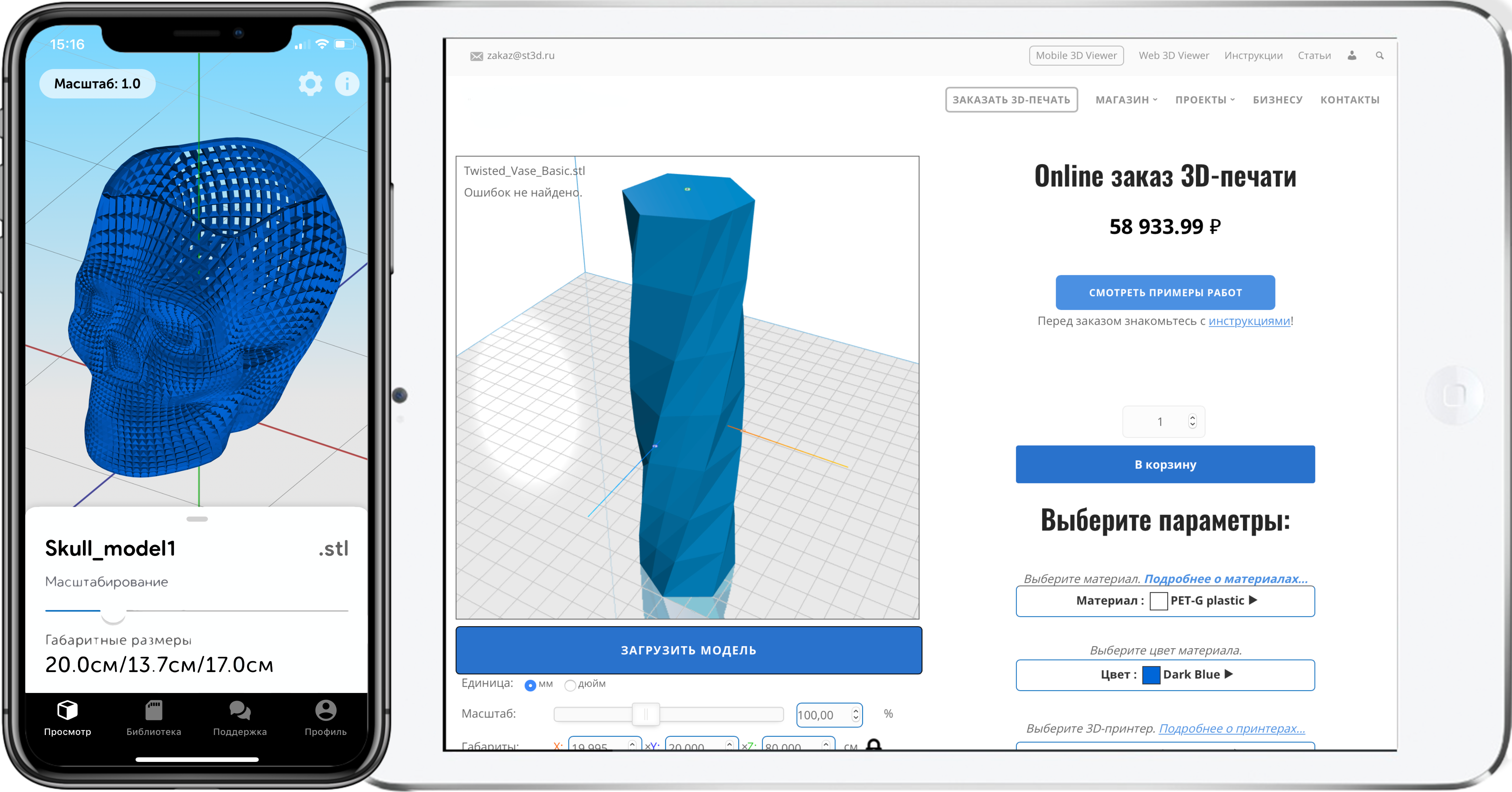


Author: Studia3D. Ru
More articles from Studia3D. Ru