In this article, we will look at the most common reasons for changing the final dimensions of manufactured products printed on a 3D printer. This article will be useful for designers and inventors to understand how to design 3D models for XNUMXD printing.
First, let's introduce some terminology. All deviations arising in the technological process of 3D printing and related technologies, we will call "error". Let's consider what types of errors are and delve into each of them.
- Extrusion width error.
- Approximation of the radii depending on the layer height.
- Positioning accuracy of 3D printer extruder.
- Inertial beats.
- Uncontrolled shrinkage of the material.
- First layer error.
- Porosity.
- Matching accuracy after printing parts, breaking down.
- Places of separation of the supporting material.
- Roughness of a thin wall.
Extrusion width error.
Preparing a three-dimensional model for 3D printing comes down to creating a so-called G-code. The G-code is a computer code that sets the movement of all the electric motors of a 3D printer. These motors include those responsible for moving the extruder (3D print head of a 3D printer). The movements and movements of the extruder are determined by the trajectory, which is determined by the line. In preparation for 3D printing, the model is divided along the Z axis into layers due to selected layer height. The trajectory of the extruder is built based on the dimensions of these layers, and in the case of the layer perimeter, it describes the outer surface of the model, averaged along the Z axis. In turn, the extruder repeats the trajectory laid down in the G-code, namely the center of the nozzle. Ultimately, when designing models, it is necessary to take into account the fact that the nozzle itself has a hole diameter through which plastic is extruded. In simple terms, the nozzle radius is added to the size of the 3D model. When choosing a 3D printer, in terms of extrusion width error, part accuracy will be higher on one with a smaller nozzle diameter. And when designing three-dimensional models for 3D printing, it is necessary to lay a margin for model widening. I want to note that in other XNUMXD printing technologies that use a laser or an illumination device, the width of the outer perimeter line depends on the focus, that is, on the thickness of the beam. As a rule, these parameters can be clarified with the manufacturer of the XNUMXD printer or with specialists. Studia3D.
Let's see how this works on the example of a three-dimensional model that has a hole.

The figure shows a 3D model, visualization of the prepared G-code and the trajectory of the center of the extruder nozzle for the 7th layer of 3D printing. Select the perimeters of the holes and put the actual width of the extrusion on the trajectory (Highlighted in light green).

As you can see, the hole diameter is smaller. How much? On the radius of the nozzle on one side + the radius of the nozzle on the other. That is, when designing a hole, I need to set a gap equal to the width of the nozzle. It's the same with all other cars. The smaller the nozzle size, the closer to the nominal size the part will be. At the same time, printing with a nozzle of a smaller diameter will cost more. This is due to performance. More plastic comes out through a larger nozzle per unit of time, which affects the print speed. The operating time of the printer, as well as the amount of material, affects the cost of receiving the product.
Approximation of the radii depending on the layer height.
The specified layer height directly affects the accuracy of 3D printing. This is clearly pronounced on the radii in the vertical sections of the model. Consider the detail from the previous paragraph, positioning it on the edge in the camera of the 3D printer.

As you can see in the figure, the hole quality depends on the selected layer height. The lower the layer height, the better the part is. In this case, it is worth considering the time of 3D printing. Increasing the layer height decreases the printing time by reducing the overall length of the path described by the extruder. Accordingly, the price for the part is reduced, because the operating time of a 3D printer directly affects the cost of 3D printing.
Positioning accuracy of 3D printer extruder.
This parameter determines the accuracy of repetition by the center of the extruder nozzle of the trajectory specified in the G-code. In other words, this parameter characterizes the maximum possible deviation of the center of the extruder nozzle from the trajectory during printing. This parameter is specified by the 3D printer manufacturer for a specific printer model. But it should be noted that this parameter corresponds to the manufacturer's recommended 3D printing speed. In turn, experts Studia3D when preparing a G-code, the influence of this parameter is minimized, but not completely eliminated. In addition to speed, this parameter is affected by the rigidity of the 3D printer and the extruder drive system.
Inertial beats.
As a special case of positioning accuracy, we single out the inertial beats that occur during three-dimensional printing as a separate item. This parameter is influenced by the same positions that were described in the previous paragraph, however, this error is reduced in a different way. This can be understood by examining the moment at which the influence of this error on the print quality occurs - a sharp change in the direction of the extruder motion vector. When the electric motors together with the drive system abruptly change the direction of the trajectory, the print head, which has some characteristic weight, continues to move in the previous direction by inertia. As a result, dynamic damped oscillations arise, which negatively reflects the surface. The influence of this error is reduced in two ways. By reducing the speed of printing the outer perimeter, which we use when printing all models, without exception, and put it at the stage of preparing the G-code. The second method is laid down when designing the model: if possible, it is necessary to add mates to the model on acute-angled edges, which, when positioning the part on the 3D printer platform, in sections parallel to the XY plane, will give sharp corners in the perimeters. As practice shows, pairing of 2 mm is considered sufficient. Show by example.

As you can see in the figure, by rounding the corner (by introducing a fillet on the face), we minimized the effect of this error.
Uncontrolled shrinkage of the material.
This parameter has its effect, as a rule, in the case of 3D printing of large objects. Large - this means more than 30% of the maximum size of the 3D printer camera along any of the coordinate axes. Most often, this error manifests itself in interlayer adhesion and a decrease in dimensions in planes parallel to XY.
Our observations have revealed approximate shrinkage for some of the most common materials in relation to cross-sectional dimensions along the parallel axes.
ABS: by XY ≈ 5%; by Z ≈ 1%
PLA: by XY ≈ 2%; by Z ≈ 0,5%
Polypropylene: by XY ≈ 7%; by Z ≈ 10%
First layer error.
The G-code preparation program considers the platform of the 3D printer to be absolutely parallel to the XY plane, however, in practice, platform calibration also has its own error. IN Studia3D the norm for the difference in thickness of the first layer is:
Δ = 0.1 mm with a layer height of 0,2 mm
Δ = 0.05 mm with a layer height of up to 0,2 mm
Porosity.
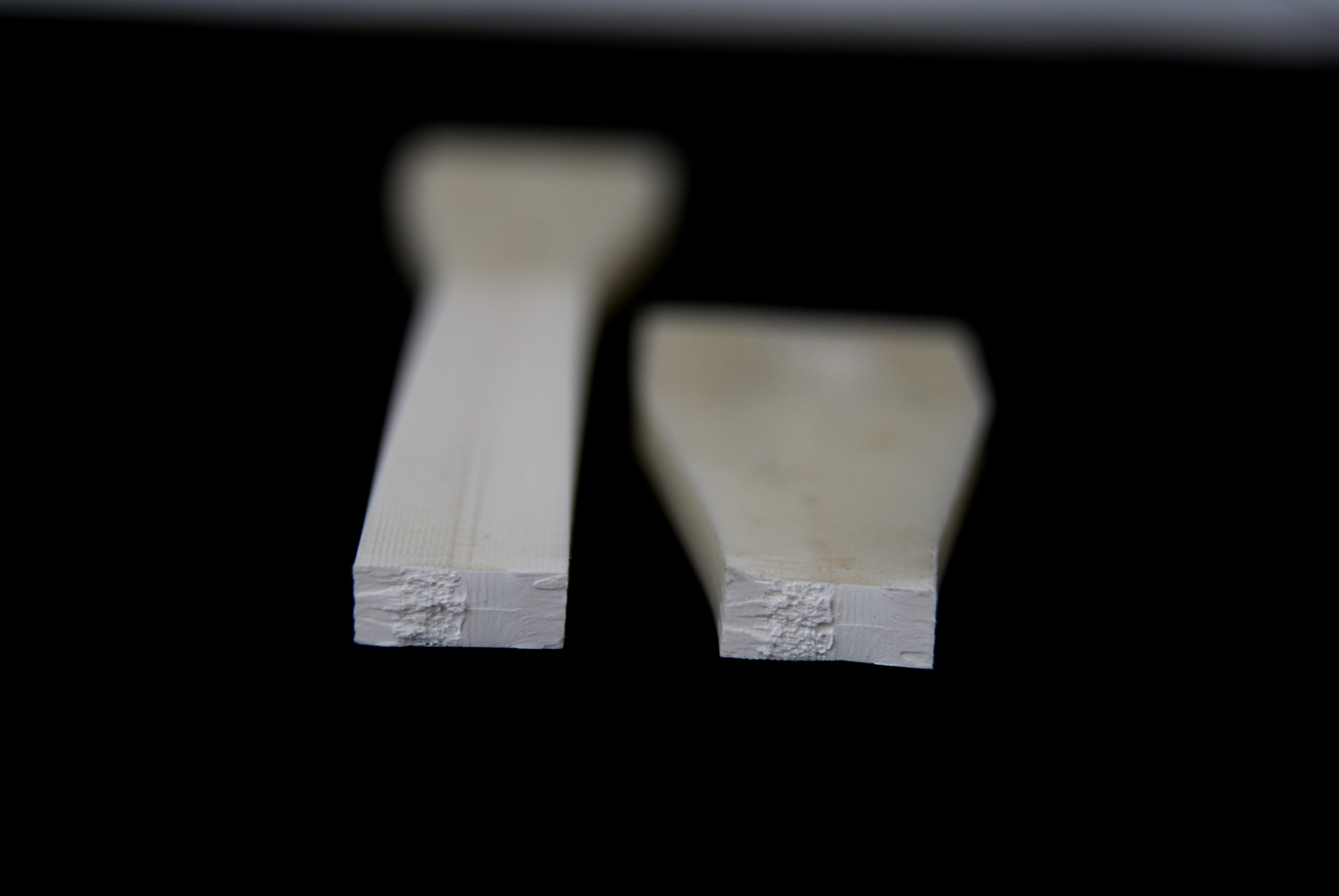
It is customary to discuss porosity in the case of 3D printing only in the case of percentage of Infill of internal slabs up to 100%. However, when printing with 100% fill, the porosity does not go anywhere.

This can be clearly seen when examining the place where the workpiece breaks through a microscope for determination of strength characteristics.
Matching accuracy after printing parts, breaking down.
If the model is not included in the printable area of the 3D printer, it is divided into components. In the best case, grooves are provided for the most accurate assembly. It should be understood that the assembly of the model from the components also affects the accuracy of the overall design. This accuracy is very difficult to assess. We accept deviations from the given model of the order of + - 2%. To fix the joint, we almost never use glue, but use special chemical solution... Ultimately, the parts do not stick together, but are soldered, only not by thermal melting of the material, but by chemical melting. As for the adhesion strength: it is higher than the adhesion between the layers. In simple terms, if you throw such a part against a wall, it will break, but primarily not at the joints.
Places of separation of the supporting material.
This item refers to supports that can be removed mechanically. Since the support material and the material of the main part consist of the same material, they are simply soldered together under the influence of temperature. Tearing off such supports leaves traces, threads, chips, etc.
To reduce this error to a minimum, it is necessary to order 3D printing with soluble supports... Due to the expensive material of soluble support, the cost of 3D printing also increases significantly. Precision, like beauty, requires sacrifice.
Roughness of a thin wall.
When preparing the G-code in a standard form, the program strives to make your part as strong as possible. This is bad only in one case, when the product has thin-walled elements. When constructing the trajectory, we set the minimum wall thickness, inside which the Infill in... Typically this thickness is equal to 3 nozzle diameters. But in cases where there are places where the thickness is less than the thickness of the outer wall, the program, when constructing the trajectory, will outline one perimeter on each side, and fill the void between them. Due to the fact that Infill will occur at a distance of 1 to 2 nozzle diameters, the extruder will begin to vibrate, an inertial runout will begin (see paragraph inertial runout). The more this distance is reduced to 1 nozzle diameter, the faster the near-resonance frequency occurs. All this negatively affects the appearance of this wall, since vibration is transmitted to the surrounding material. Let's see clearly.

To minimize this error, it is necessary to design the part in such a way that the wall thickness is a multiple of the nozzle diameter. The difference is on the face!

Output.
In conclusion, I want to note that when designing three-dimensional models for 3D printing, it is necessary to take into account the totality of all factors affecting the accuracy of products, and not consider any particular one. Team Studia3D every day we work to ensure that the 3D printing process is completely predictable and controllable, however, like any kind of production, 3D printing has its own precision. There are no ideal sizes. Therefore, we are very pleased if, in addition to three-dimensional models, a working drawing of the product is provided, where all fits, tolerances, roughness, etc. are indicated. Only in this case we can choose the technology, properly prepare the G-code and guarantee the quality laid down by the designer. In other cases, before starting a batch, it is necessary to make “sighting” seals, having examined and selected the necessary parameters.





Author: Studia3D aggregator
More articles from Studia3D aggregator