NATIONAL STANDARD OF THE RUSSIAN FEDERATION
ADDITIVE TECHNOLOGICAL PROCESSES
BASIC PRINCIPLES - Part 3
General requirements
Date of introduction - 2017-12-01
- Application area
This International Standard specifies basic terms and definitions for data exchange in additive manufacturing. This International Standard defines terms and definitions for describing the geometry of a product or parts of it in additive manufacturing, describes data exchange methods, file types and formatting.
This standard:
- describes suitable data exchange formats used in additive manufacturing processes:
- describes the existing formats for the development of ZO-geometry for additive manufacturing;
- describes the existing file formats used within modern additive
production; - provides an understanding of the necessary data exchange functions for harmonization with international standards.
This International Standard is intended for users and manufacturers of additive manufacturing processes and related software systems. It is used wherever additive processes are used, in particular:
- in the use of products of the system of additive technologies and equipment, including software;
- in the field of software engineers. working in CAD / CAE systems:
- in the field of developers of reverse engineering systems;
- control bodies that establish the compliance of design and actual values of the geometry of the product.
- Normative references
This standard uses normative references to the following standards:
GOST R57558—2017 Additive technological processes. Basic principles. Part 1. Terms and definitions
- Terms and definitions
In this standard, the terms in accordance with GOST R 57558—2017 are used.
Official edition
- Data exchange
- Data stream
- General provisions
- Data stream
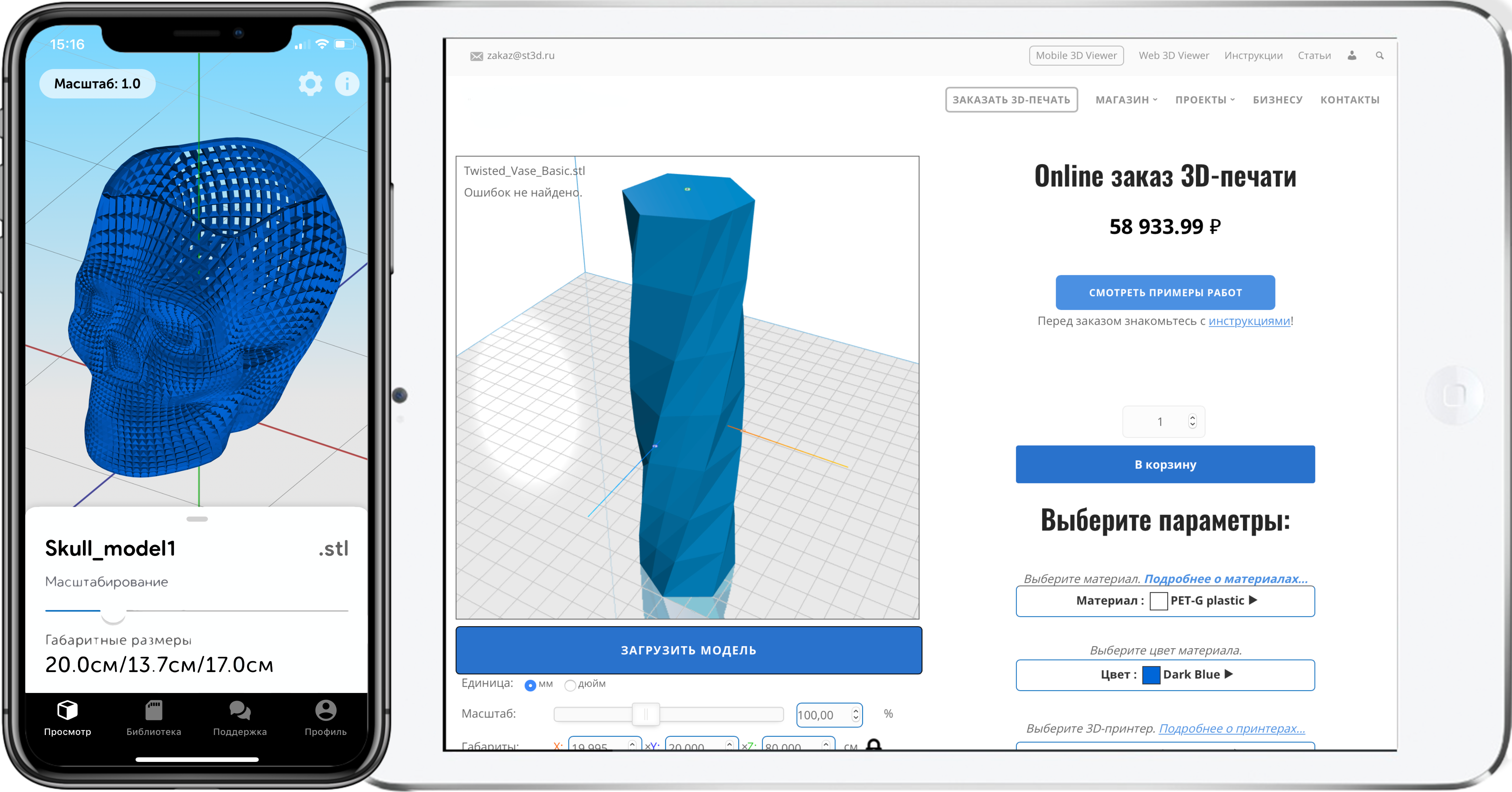
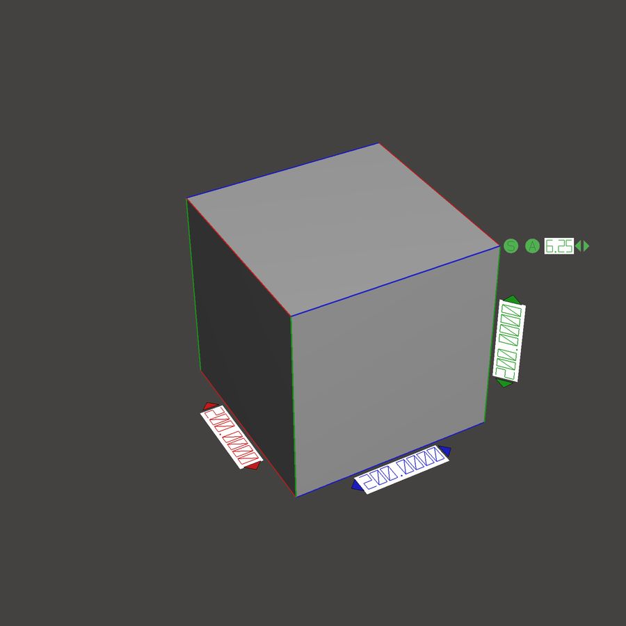
The complete 3D dataset of a part of a product forms the basis of additive manufacturing. This is most often created by direct 1D modeling in CAD systems. Datasets can also be derived from measurements if parts of the parts exist in physical form (see Figure XNUMX).
Data representation is based on product faces, then generated from the volume or area of the model through polygonization or triangulation (see 4.1.2.4) and transmitted during production in STL or VRML format (see 4.2.2 and 4.2.3). The software facilitates the automatic execution of the process as much as possible.
- Explanation of key terms used in Figure 1
- 3D CAD modeling (volumetric modeling)
3D CAD modeling is the process most commonly used in design to generate a digital ZO model. The starting point can be an image of a product that takes shape and becomes more and more defined directly on the computer screen, or a previously created image of an object in the form of sketches, drawings, etc., which are then simply converted into XNUMXD data. The volume of an item can be described using two different methods or a combination of both. An object consists either of elementary volumes (shapes) (for example, a rectangular parallelepiped, prism, cylinder, cone, sphere and toroid) that generate a real object using a sequence of logical operations, or a volume that describes its neighborhood of the boundary surfaces and the arrangement of materials relative to the boundary surfaces
- XNUMXD-digitization (reverse engineering)
3D digitizing is a process in which the surface geometry of a physical object is determined using appropriate hardware and software and points recorded in a digital model. Objects can be recorded by hand or ready-made models can be used, which must be digitally copied. The use of XNUMXD-digitization is especially effective. if the model has an empirically developed, free surface, since it is difficult to reproduce using direct modeling in XNUMXD CAD.
- Surface reconstruction
Surface reconstruction is a means of processing data obtained using XNUMXD digitization. Starting with arrays of points, mathematically described curves and surfaces are created.
An object surface with sufficient topological information is generated. This data can then be stored separately or integrated into an existing XNUMXD CAD model. Reengineering creates a bridge between XNUMXD digitizing and CAD modeling.
- Polygonization / triangulation
This additive process software is used to create a volumetric model from facet data either from a point array after XNUMXD digitizing or using a XNUMXD model after XNUMXD CAD modeling. The surface of an object is a set of tiny, flat faces or polygons that extend between points. The number and size of the facets determine how accurately the surface geometry is reproduced. This process creates a dataset in STL format.
- Slicing process
The slicing process is an important preconditioning step in all additive manufacturing processes. It involves slicing the facets (volume) of the model into several sequential layers and recording the information contained in each layer. If the cut contour data is no longer connected to each other in the Z-axis, subsequent scaling is no longer possible. With some technologies, this process is performed automatically by the software as soon as the necessary parameters (for example, layer thickness) have been set. Other systems require separate software to prepare and store this layer data.
- Data formats
- General provisions
STL format is the standard format for transferring data. Some systems can read and process data in vrml format.
If the data formats cannot be exported to the STL format due to the absence of an interface module (not included in the standard delivery of the CAD program), then the data can be transferred to other CAD programs through the interface formats (for example, in the IGES or vda format), which then includes STL exit.
NOTE - Conversion problems can arise when transferring data through system-neutral interfaces, since the capabilities of the interfaces (despite the established standards) differ significantly and the programs work with varying degrees of accuracy.
- STL
The STL (Surface Tessellation Language or Stereolithography) file format has established itself as an industry standard format for transferring data in additive technologies. It is a system-neutral geometric coordinate data exchange format. The boundary surfaces of the volumetric model are described by triangles (planar faces) and their normal vectors. Sets of STL files can be saved using ASCII or binary representations, which are a more readable format that greatly reduces file size. The STL format is not suitable for data exchange between CAD systems.
- VRML (WRL)
VRML (Virtual Reality Modeling Language) is a platform independent language that supports 30D rendering and various networking capabilities. VRML is a data format that is not limited to entry points or extremes in the form of lists. The data format describes 8 objects or scripts in an object-oriented way in a single computer language (plain ASCII or utf-3 text). The main components of the VRML format are node types and communication channels. Types of nodes are built on basic geometric shapes such as rectangular parallelepipeds, cylinders, cones, spheres. It also uses node cameras (parallel perspective) and node groups to implement hierarchical structures, as well as prototypes. to expand the existing range of node types. More recently, VRML has become XML. expandable 3D. WebXNUMXD.
- IGES
IGES is a neutral data format and international standard for exchanging CAD data between different CAD systems. IGES was developed mainly for the transfer of geometric data related to 2D drawing model and ZO surface model. IGES uses volumetric elements (rectangular parallelepipeds, cylinders, spheres, etc.). about 40 additional geometric elements (surfaces, curves, arcs, points, interaction systems, etc.) and more than 35 non-geometric elements (text, dimensions, tolerances, etc.).
- VDA-FS
VDA-FS (Verband Der Automobilindustrie-Flachenschnittstelle) is the standard CAD interface of the VDA (Association of German Automobile Manufacturers). It is primarily intended for the exchange of bodywork data. VDA-FS is well suited for the exchange of freeform surface data that has been generated using surface-oriented 3D software. Points, point volumes and vectors can also be transferred in this format.
- STEP
STEP (Standard for the Exchange of Product Model Data) is a neutral format system, an interface for describing and exchanging product model data between different CAD systems. STEP can be used to transfer product data (for example: colors, text, or support layer) in addition to geometric data (like DXF or IGES).
The CAD data model can be integrated into geometric representation (wireframes, surface volume models, and other models).
- AMF
Manufacturing Additive Format AMF is an XML-based data format. Specially formulated to meet the needs of additive manufacturing. As with the STL. there is a mosaic description of the surface of the part (or parts), but additional data, such as material, texture, color, is already included.
4.3 Data preparation
- Importance of data quality
Flawless reproduction of geometry in the STL dataset is a prerequisite for ensuring a high-quality, smooth manufacturing process of parts using existing manufacturing technologies. Particular attention should be paid to the following:
- all surfaces of the model must be perfectly matched (perfectly sealed, waterproof model);
- all surfaces must be oriented in such a way that volumes can be clearly defined;
- when performing triangulation, the surfaces of structures (layers, cylinders, axes, no-show elements, etc.) must be selected;
- surface models should ideally be converted to solid forms before polygonizing / triangulating.
Generating or supplying poor quality data can complicate data set or recovery, which in some cases can be very time consuming and costly. Therefore, an individual agreement of the drawings with the customer is required.
- STL export options
Setting export options when entering STL data and. therefore, the accuracy of polygonization / triangulation determines how accurately the approximation is given to the geometry of the product. Too low a resolution affects the accuracy and appearance of the finished prototype. However, very high resolution requires a lot of memory (excessive file size) and increases preparation time (see table 1).
| Table 1 - Possible formatting errors in the STL dataset and their impact on the manufacturing process and parts
|
Various data export options can be set depending on the CAD program:
- chord height, aspect ratio and resolution:
- surface geometry value, absolute surface alignment, absolute deflection in facets, maximum deflection distance, etc .;
- triangle geometry value tolerance, angle tolerance, angle control, surface, angle, etc.
For several programs that do not allow individual parameters to be set when exporting data, the output parameters are configured by display parameters. In this case, you should take care of that. to ensure adequate value and high resolution of the display in the program, achieved by the preliminary adjustment.
The increase in the number of edges improves the quality of the image, but cannot be achieved without significant costs. As a rule, you can subsequently reduce the number of faces without causing problems with reproducing individual parameters.
- Features of data processing
- Machining allowances
Additional processing may be required depending on the component and the manufacturing method chosen. In this case, it is important to ensure proper oversizing by increasing the nominal size in the relevant areas when creating the CAD model. The contractor / manufacturer must additionally analyze the treatment areas.
- Volume reduction (mass reduction)
Some additive manufacturing technologies can be very time consuming and expensive to manufacture in large volumes. However, it is very often possible to reduce the size of the CAD model in areas where, for example, cavity machining with tools is required. This should be taken into account at the design stage. Volume reductions must be agreed in advance when executing a production order.
- Positioning time
Depending on the process, positioning occurs in three construction coordinates and varies to obtain different characteristics. This must be taken into account when aligning geometry in the construction of space. In addition, production times are often positioned dependent.
Certain manufacturing processes require the use of additional supports to support the overhanging "underneath" geometry. They are installed prior to production and. are usually removed manually after completion of the production process.
The system user provides user support or creates options in the software system or individual tools to build an optimal build process.
It is not always possible to avoid damage to a completely finished surface when there is support. For such cases, you should mark the places where it is necessary that the support is not attached.
UDC 774: 002: 006.354
OKS 71.020
71.100.01
77.160
Key words: additive technologies, adoptive technological processes, materials, basic
principles
Published and printed by FGUP STANDARTINFORM. 123001 Moscow. Granatny lane, 4.


Author: Studia3D. Ru
More articles from Studia3D. Ru