Delta printers are extremely demanding on the accuracy of manufacturing components (frame geometry, length of diagonals, gaps in the connection of diagonals, effector and carriages) and the entire geometry of the printer. Also, if the limit switches (EndStop) are located at different heights (or a different actuation moment in the case of contact limit switches), then the height along each of the axes is different and we get an inclined plane that does not coincide with the plane of the working table (glass). These inaccuracies can be corrected either mechanically (by adjusting the limit switches in height) or programmatically. We use a software calibration method.
Next, the basic settings of the delta printer will be considered.
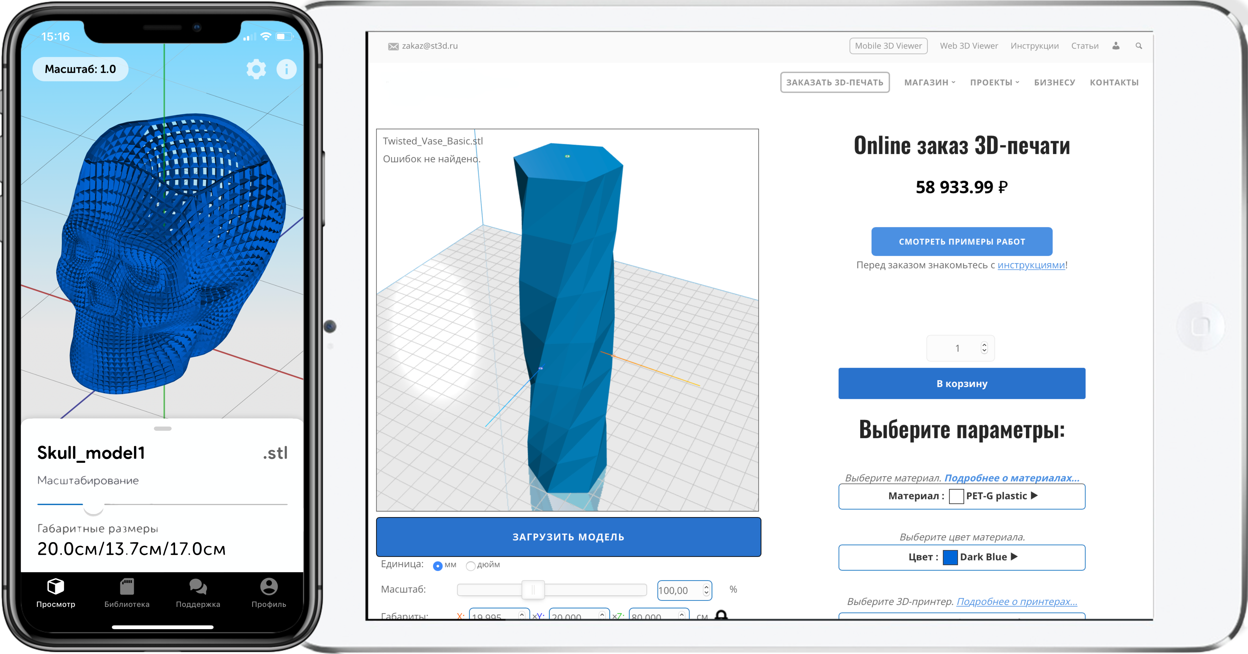
To manage and configure the printer, we use the program Pronterface.
Printer calibration is divided into three steps:
- Correcting the plane by three points
- Fixing the lens
- Finding the true height from the nozzle to the table
Repair and setup of 3D printers
Stage 1. Correctioneat a plane by three points
Alignment of three points in one plane - A, B, C (located next to the three guides). In fact, it is necessary to clarify the height from the plane to the limit switches for each of the axes.
Most (if not all) boards for controlling a 1.4D printer (RAMPS XNUMX in our case) work in a Cartesian coordinate system, in other words there is a drive on the axis: X AND Z.
In the delta printer, you need to change from Cartesian to polar coordinates. Therefore, we agree that those connected to the engines X AND Z corresponds to the axes A, B, C. (Counterclockwise starting from any engine, in our case, looking at the logo on the left - XA, on the right YB, far ZC). Further, when slicing, printing and managing the printer in manual mode, we will operate with the classical Cartesian coordinate system, the printer electronics will itself recalculate the data into the system it needs. We need this convention to understand the principle of operation and direct calibration of the printer.

The points by which we will perform the calibration will be called similarly (A, B, C) and the position of these points is equal to A= X-72 Y-42; B=X0Y84; C=X72 Y-42.

Setting algorithm:
- We connect to the printer. (In case of “unreadable characters” on the command line, you need to change the speed of the COM port. In our case, from 115200 to 250000 and reconnect).

After that we will see all the printer settings.

2. Reset the heights of the X, Y, Z axes with the command M666 x0 y0 z0.
And save the changes with the command M500. After each change of settings, you must press home (or the command g28) so that the printer knows where to take the reading from.
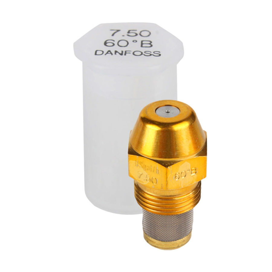
3. The printer is calibrated “hot”, that is, the table heating (if any) and the heating of the print head (HotEnd) must be turned on (Table 80 degrees, nozzle 245 degrees). We also need a probe, preferably metal, of known sizes. For these tasks, a hex wrench is quite suitable.
4. We lower the print head to a height (conditionally) of 9 mm from the table (so that the nozzle barely touches our probe, because the height has not yet been accurately set.) Command: G1 Z9.
5. Now we proceed directly to setting up our three points.
For convenience, instead of g-commands, you can create in Pronterface four buttons, to move the print head to points A, B, C, 0-zero.
Creating Buttons in Pronterface
To do this, in the central part of the window there is a “+” button, by clicking on which a window with three fields will open: Button Title (Button name), Command (command), Color (Color of the future button).

We fill in:
Buttom Title: Min A; Command: G1 X-72 Y-42; Color: Orange
Buttom Title: Min B; Command: G1 X0 Y84; Color: Blue
Buttom Title: MinC; Command: G1 X72 Y-42; Color: Green
Buttom Title: zero; Command: G1 X0 Y0; Color: White
6. Sequentially moving between three points (previously created buttons or commands), we find out which of them is the lowest (visually) and takes this axis as zero, relative to it we will change the height of the remaining two points.
Let's assume that point A is lower than the others. We move the head to point B (Y) and use the height control keys in Pronterface to lower the nozzle until it touches our probe, counting the amount by which we lowered the nozzle (on the forehead we count the number of clicks on the +1 and +0.1 buttons)
7. Next, change the height parameters of the Y axis with the command: M666 Y {calculated value}
M666 Y0.75 (after Y is your value)
M500
G28
We do the same operation with the remaining axes. After that, you should check the height of all points again, it may turn out that the height spread after the first calibration will decrease, but the height will still be different, while the lowest point may change. In this case, repeat steps 6-7.
2 Stage. Fixing the lens
After we have set three points in one plane, it is necessary to correct the height of the central point. Due to the peculiarity of the delta mechanics, when moving the print head between the extreme points in the center, it may pass
either below or above our plane, thus we get not a plane, but a lens,
either concave or convex.
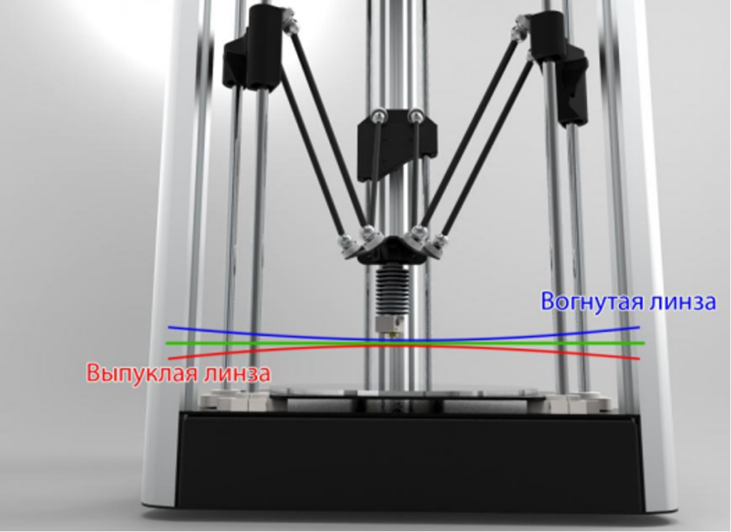
This parameter is adjusted by the so-called. delta radius, which is selected experimentally.
Calibration:
We send the head to the height of the probe to any of the three points on the table. For example G1 Z9 X-72 Y-42.
Compare the height of the center point and the height of points A,B,C. If the height of points A, B, C is different, it is necessary to return to the previous calibration.
If the height of the central point is greater than the rest, then the lens is convex and the delta radius value must be increased. It is desirable to increase or decrease in increments of +-0,2 mm, if necessary, reduce or increase the pitch depending on the nature and magnitude of the curvature (selected experimentally).
Teams:
G666 R67,7 M500 (in R you need to write your value)
G28
We adjust the delta radius until our plane is aligned.
3 Stage. Finding the true height from the nozzle to the table
In the third stage, we adjust the print height (from the nozzle to the lower plane - the table). Since we believed that the overall height is obviously wrong, it is necessary to correct it, after all the adjustments of the heights of the axes. There are two ways to solve this problem:
1 way:
By manually fitting our nozzle under the probe so that it passes freely under it, but there is no noticeable play,
Team M114 display the value of the actual height of our HotEnd
Team M666L get the total height value (Parameter H)
Then subtract the actual height from the total height.
The resulting value is subtracted from the height of the probe.
Thus, we get the amount of nozzle shortfall to the bottom plane, which must be added to the total height value and written to the printer's memory with the commands:
G666H 235.2 (after H is your value)
M500
G28
2 way:
Simple “by eye” we add the value of the height (after each change, do not forget to “leave” to home), achieving the necessary.
Did not find an answer to your question?
You can write to support so that our specialists will individually consider your issue. In the request, describe in detail the essence of the problem.


Author: Studia3D aggregator
More articles from Studia3D aggregator