At present, additive technologies are positioned as technologies that can largely replace traditional approaches to the manufacture and repair of mechanical engineering parts [1]. The accumulated experience shows that the use of technologies of "three-dimensional printing" (3D-printing) allows you to create products in the shortest possible time and with minimal loss of material.
The technology of 3D printing is based on the creation and use of a digital 3D model of the resulting product. This model can be formed both in the process of its design using the appropriate software, and by scanning damaged components of assembly units of the machine (using a XNUMXD scanner) with subsequent computer processing of the results. The presence of a digital model significantly increases the speed and accuracy of parts production.
Due to the current practice of widespread use of computer networks, during additive manufacturing and restoration of parts, the developer of their electronic copy can be at any distance from the object (machine). This allows a qualitatively different approach to the organization of additive manufacturing of diverse products and opens up prospects for the creation of universal multifunctional production and repair complexes based on 3D printing.
For the widespread introduction of additive technologies in mechanical engineering, it is necessary to accumulate experience in the creation of specific engineering products and to show the effectiveness of this approach. An innovative method of developing a 3D printing technology for the production of track rollers for all-terrain vehicles, which this work is devoted to, is devoted to solving this particular problem.
1 Analysis of the use of the 3D printing method for obtaining mechanical engineering products
1.1 Analysis of existing areas of application of 3D printing in the Russian market
Prototypes of the first 3D printers emerged back in the 90s of the last century, but they gained wide commercial distribution only in the early 2010s, when manufacturers realized that they could be used for small-scale production [2]. Around the same time, additive technologies began to develop in Russia. The first domestic companies began developing their own 3D printers. 3D printing became more widespread about 5 years ago, then companies began to appear that allow you to print the desired part without purchasing your own 3D printer.
At the moment, 3D printing in Russia is gaining momentum. It is not a novelty for a long time that functional products are made by 3D printing, both capable of carrying a load and not. 3D printing is used to produce parts in aviation, rocketry, automotive, medicine, jewelry, prototyping, design and others.
3D printing is a very flexible technology. Perhaps, in every field there is a place where 3D printing technologies could be applied. There are over 200 different 3D printing technologies. Currently, when we talk about 3D printing, we are primarily interested in the material from which the part will be made. Depending on the properties of the material, we can select the optimal 3D printing technology. Each application has its own criteria that must be met by parts made on a 3D printer: accuracy, roughness, strength, weight, etc.
For aviation and rocketry, parts must be strong, lightweight, accurate, and have special properties inherent in the given object. In these areas, so-called engineering plastics and metals are commonly used. The addition of various elements for plastics can improve the properties of the material in the required conditions. Various filaments with polycarbonate, mixtures of plastics with other materials for 3D printing, polyamides, materials PEEK, PEI, PPSF, PSU [3] are able to work in harsh conditions and meet the requirements of aviation. Many companies use 3D printing for the production of prototypes, interior parts, aircraft skin, and utilities.
One cannot fail to mention the use of 3D metal printing in aviation and rocketry. Metal 3D printing allows you to achieve special properties of metals due to the principle of combining dissimilar metal powders. This technology, in contrast to casting, allows you to obtain a more complex shape of an object without high material and labor costs. In addition, 3D printed metal products do not have porosity that can interfere with the quality of the casting.

Figure 1 - Bracket for S7

Figure 2 - Bracket for S7
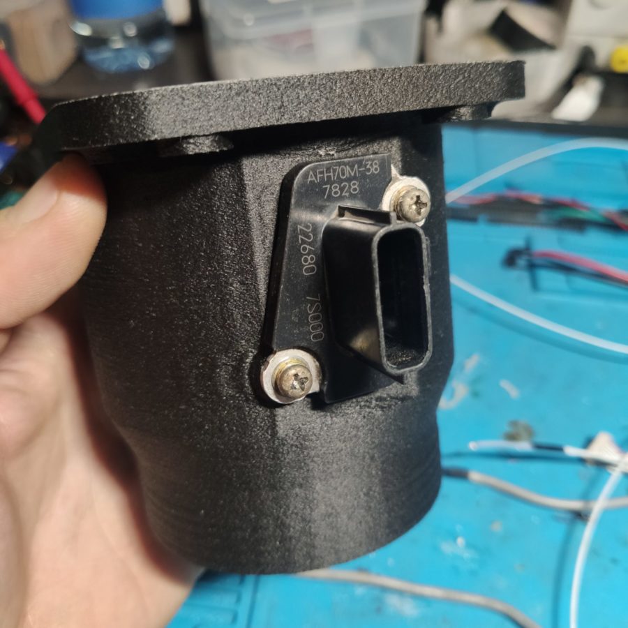
The experience of using 3D printing in the production of Russian cars lies in the creation of Aurus cars of the Cortege project, in which 3D printing technologies were used. Some parts were first printed from plastic, then using the printed master model by injection molding, working parts of the optimal shape were made, which surpass their counterparts in other world companies in terms of weight characteristics. In addition, some of the parts were manufactured using 3D metal printing. Figure 3 shows an SLM nozzle.

Figure 3 - The pipe in the car Aurus, made by 3D printing
The use of 3D printing in medicine is currently quite widespread, but due to the lack of certification for products made by 3D printing, this area is not becoming more widespread. Nevertheless, at the moment, 3D printing is used in surgery, and in prosthetics, and in dentistry, technologies are being developed that can print organs or parts of the body (Figure 4).

Figure 4 - Model of the spine of the animal for the operation
So, in 2017, for the first time in Russia, a surgical operation was performed to transplant a bone implant, printed on a 3D printer. A group of doctors led by Professor Georgy Gafton saved the patient from a cancerous tumor in the pubic bone for three and a half hours [4]. The implant was made by Endoprint, a 3D-printed surgical implant company (Figure 5). A titanium implant based on MRI and CT scans was placed in the bone.

Figure 5 - An example of the manufacture of an implant using 3D printing
In Russia, the GS3 corset was invented, it was made using the 3D printing method (Figure 6). The peculiarity of the corset is that with the help of gyroscopes and accelerators, the corset adjusts to the movements of the person, providing back support without discomfort.

Figure 6 - Corset GS3, with the possibility of individual adjustment
Dentistry is an area where 3D printing is widely used in the creation of inlays, onlays, crowns, veneers, special mouth guards, etc. The materials used in 3D printing for dentistry are highly biocompatible, accurate and have low surface roughness. In addition, the material can be selected in accordance with specific requirements, which improves the quality of service and the durability of the objects used (Figure 7).

Figure 7 - Dental aligner made by 3D printing from NextDentOrthoClean
One of the sides where 3D printing can still be used in medicine is the manufacture of various organs, body parts, guiding doctors for training doctors before an important operation. Cases when, according to MRI and CT, a skull or bones of a person or an animal is made for the practice of a surgeon are no longer uncommon (Figure 8) [5].

Figure 8 - Surgical template for the operation on the bones of the animal, made by the company "Studia3D»
In addition to the use of 3D printing in areas that are important for human life and the development of society, technology is used for aesthetic purposes. For example, jewelers have long used photopolymer printing to create special jewelry. The 3D printing method allows you to create any shape, make a mold for casting, and then create various things from it (Figure 9). Often, jewelry can be created by another method - by sintering precious metal powder. This method bypasses mold creation and subsequent casting and allows for more complex and incredible shapes.

Figure 9 - Jewelry made from a model printed on a 3D printer
The creation of collectible and gift coins is one of the areas related to jewelry. The master model is made according to the same principle, according to which the mold for casting and the finished coin is cast.
The aesthetic applications of 3D printing don't end there. Model workshops have appreciated the 3D printing technology and are actively using it in their projects. The creation of models of houses, technical devices (Figure 10), landscape design, models of government agencies and transport hubs (Figure 11) - all this is now easier and faster to manufacture thanks to 3D printing. Products for mock-ups are not subject to high strength criteria, but in this area, accurate drawing of details is important. Therefore, objects of models are made from both plastic and various photopolymers.

Figure 10 - Model of an electric generator for visualizing the concept of a new product, made by the company "Studia3D»

Figure 11 - Model of the Makhachkala port, made by the Scale company together with "Studia3D»
Design is one of the largest uses for 3D printing. It is believed that 3D printing is intended only for the manufacture of non-functional and decorative items, but as we can see above, this is not the case. Nevertheless, design applications of the technology are widely used, and 3D printing has become the favorite of many decoration companies. Exhibition stands of events, statues with a height of 1,5-2 meters (Figure 12), statuettes for awards for competitions (Figure 12), gift sets of a specific theme and limited edition, and much more - where 3D printing is now used in design.

Figure 12 - Statue of a cartoon hero with a height of 2,5 meters (left) and awards for the film festival (right)
1.2 Advantages and disadvantages of 3D printing in the manufacture of mechanical engineering products
Each manufacturing technology has its own advantages and disadvantages. The extent to which the advantages in certain conditions prevail over the disadvantages of technology determines its feasibility and effectiveness. Speaking about the direct advantages of 3D printing as a technology, the following can be highlighted: cheaper production, lighter weight of the product while maintaining characteristics, high speed of small batch production.
How 3D printing helps to reduce the cost of production: the presence of a 3D printer implies the use of smaller production areas, less equipment of production with equipment in comparison with traditional processing methods. Often, a 3D printer requires only room temperature, electricity, a minimum set of tools for maintenance and calibration, not counting the basic elements in the form of consumables and additional components. For certain types of machines, additional cooling is required or, conversely, maintaining the optimal temperature, special tools, more complex maintenance in comparison with personal 3D printers, for example. The reduction in production costs occurs mainly due to the principle of additivity, due to which much less material is consumed than in traditional production. Due to the ability to get any shape without using a variety of methods, 3D printing is popular for the manufacture of atypical parts or products. In addition, a number of reasons that can reduce manufacturing costs include the fact that 3D printing is able to produce a small series of parts without designing, for example, casting molds or creating special tooling. If in the design process a mistake was made or the preferences or characteristics of the manufactured product changed, then the cost of making a sample in 3D printing is much lower than other types of production.
One equally important advantage of the aforementioned advantages is the high production speed of 3D printing. 3D printing itself, as it might seem at first glance, is a long process, which involves the passage of an extruder nozzle or a laser a given trajectory a huge number of times. But do not forget about the actual preparation time of the product for 3D printing, the time of the 3D printer operator to prepare the g-code, 3D printing of a complex product in one "setup" - all this has a positive effect on the part production time. Naturally, for simple products or mass production in the case of injection molding machines, 3D printing does not offer a time advantage, but when it comes to complex shapes and small series, 3D printing is the clear favorite.
At the heart of 3D printing is the concept of getting any product shape. With proper handling of this tool and taking into account all the accompanying factors, the following advantages can be clearly highlighted:
- Manufacturing speed
- Production in one setup
- Minimizing the risks
- The ability to obtain products of complex shapes
- Wide range of applications
- Technology availability
1.3 Analysis of the most common 3D printing materials
3D printing is the process of shaping a product by applying a material. 3D printing technology is selected depending on the selected material and is determined by the chemical composition of this material. The most common materials in 3D printing are thermoplastics, photopolymer (light-cured) resins, polyamide, and metals.
At the moment, there are more than 200 3D printing technologies, each technology is due to the base material and the presence of additives or inclusions as Infill. All technologies, one way or another, are reduced to four basic ones:
- In the case of thermoplastics, layer-by-layer application of the material by extruding the polymer through a die and bonding the next layer to the previous one by means of adhesion. Adhesion is due to intermolecular interactions in the surface layer and is characterized by the specific work required to separate surfaces. Figure 13 shows a special case of 3D printing with thermoplastics - FDM technology.
Figure 13 - A special case of FDM3D printing
- In the case of photopolymer resins - layer-by-layer curing of a liquid photopolymer by hitting it with photons. It is considered the most optimal from the point of view of obtaining high-precision products. Figure 14 shows a diagram of the method of 3D printing with photopolymers using the example of SLA technology.

Figure 14 - A special case of photopolymer 3D printing using the SLA method
- In the case of powder non-metallic printing - selective sintering of preliminarily thin layers of material with a laser beam. Figure 15 shows a diagram of 3D printing with non-metallic powder using the SLS technology.

Figure 15 - A special case of SLS3D printing
- In the case of powder metal printing - selective melting by a laser beam of previously thinly laid layers of metal powder. Figure 16 shows a schematic of metal 3D printing using SLM technology.

Figure 16 - A special case of SLM3D printing
A characteristic and pronounced feature of parts printed on a 3D printer is the texture of layering on the surface of the product.
1.4 FDM 3D printing technology
Currently, for the manufacture of mechanical engineering parts, 3D printing technologies are most often used with metals and, to a lesser extent, polyamide and photopolymer. However, there is an FDM technology for 3D printing with thermoplastics, which was not previously considered as a method of manufacturing engineering parts. In our work, we decided to investigate the possibility of using this technology to obtain mechanical engineering products, since it has a number of advantages.
Firstly, FDM technology is most widespread due to the relatively low cost of equipment and consumables.
Secondly, this technology is the easiest to set up and service 3D printers. In this case, we consider this technology as a direct competitor to injection molding machines for small-scale production.
Let's take a closer look at the technology. The process itself is the process of creating an object by depositing a molten filament in the working chamber of a 3D printer. 1988D printing technology, in which the construction of the object is due to the melting of the plastic filament, which is fed through the extruder to the working surface. It was developed by the American company Stratasys in 17. Figure 3 shows a diagram of XNUMXD printing using FDM technology.

Figure 17 - Principle of material construction with FDM 3D printing technology
FDM is the most affordable and widely used 3D printing technology in the world. This technology is used by both cheap home and personal 3D printers and industrial high-precision machines. As a rule, relatively large products are manufactured using this technology, which must have reliable mechanical properties (strength, wear resistance, flexibility). The main advantage of this technology is the low cost of consumables. And the consumable itself is great for post-printed processing of products. Products obtained by the FDM3D printing method are usually monochrome, strong and resilient, have a stable set of physical characteristics, which depend on the type of material. They can be heat-resistant, wear-resistant, have increased flexibility or toughness, etc.
The accuracy of building models using FDM technology largely depends on the thickness of the printed layer and the accuracy of positioning the extruder relative to the platform. This value can be between 0,02 and 1,2 mm. The surface of the finished objects is ribbed (stepped - in the range of 0,02 - 1,2 mm). Ribbing is due to the fact that the molten thread has a rounded shape. You can add additional smoothness to the surface using post-processing.
FDM technology (Fused deposition modeling) implies the creation of three-dimensional objects by applying successive layers of material that follow the contours of the digital model.
The production cycle begins with the processing of a three-dimensional digital model. The model in .stl format is divided into layers and oriented in the most suitable way for printing. Supporting structures are generated as needed to print overhanging elements. A control program for a 3D printer is prepared in special software.
The model is produced by extrusion (“extrusion”) and the application of molten thermoplastic with the formation of successive layers that solidify immediately after extrusion. How the material is extruded is shown in Figure 18.

Figure 18 - Principle of feeding plastic into the extruder
The plastic filament is unwound from the spool and is introduced into the extruder - a device equipped with a mechanical drive for filing the filament, a heating element for melting the filament and a nozzle through which extrusion is carried out directly. The heating element is used to heat the nozzle, which in turn melts the filament and feeds the molten material to the surface of the working table (for the first layer) or to the previous layer, connecting with it. Typically, the top of the nozzle is, on the contrary, cooled by a fan to create a sharp temperature gradient necessary to ensure a smooth flow of material.
The extruder (also called the "print head") moves horizontally and gradually applies the desired layer, after which it moves vertically (most often by lowering the table, but there are models in which the extruder is raised) by the layer thickness and the process is repeated until the model will not be fully built.
FDM printers use thermoplastics as printing materials, in the form of thin filaments wound on spools. The range of plastics is very wide. Some of the most popular plastics for printing are PLA, ABS. PLA is a material that is made from corn or sugarcane, which makes it non-toxic and environmentally friendly, but makes it relatively short-lived. ABS is very durable and abrasion resistant, although it is susceptible to direct sunlight and can give off small amounts of harmful fumes when heated.
In addition to PLA and ABS, printing is possible with nylon, polycarbonate, polyethylene and many other thermoplastics widely used in modern industry. It is possible to use a material such as polyvinyl alcohol (PVA-plastic). This material is soluble in water, which makes it very useful for printing models with complex geometric shapes.
It is also possible to use composite materials that imitate wood, metals, stone. Such materials use all the same thermoplastics, but with admixtures of non-plastic materials. Thus, Laywoo-D3 consists of 40% natural wood dust, which allows printing “wood” products, including furniture.
The material called BronzeFill is filled with real bronze, and the models made from it are amenable to grinding and polishing, achieving a high similarity with products from pure bronze.
The bonding element in composite materials is thermoplastics, which determine the thresholds for strength, heat resistance and other physical and chemical properties of finished models.
FDM is one of the least expensive printing methods and is driving the growing popularity of consumer printers based on this technology. In everyday life, 3D printers using FDM technology can be used to create a wide variety of special purpose objects, toys, jewelry and souvenirs.
The advantages of FDM technology include:
- easy to operate, so even non-professionals can easily handle printing;
- in the process of modeling, high-quality parts are created with high detailing of complex geometric shapes and cavities;
- sufficient cheapness of consumables;
- a wide range of colors and types of plastic.
The disadvantages of this technology include:
- low speed of work (other technologies cannot boast of high speed of work either. It takes a lot of time to build large and complex models);
- low resolution both horizontally and vertically, which leads to a more or less noticeable layering of the surface of the manufactured model;
- problems with fixing the model on the desktop (the first layer should stick to the surface of the platform, but so that the finished model can be removed). This problem can be solved in different ways: by heating the desktop; applying various coatings to it;
- for overhanging elements, the creation of supporting structures is required, which subsequently have to be removed. Even taking this into account, some models simply cannot be made on an FDM printer in one cycle and you have to break them into parts and then join them together by gluing or in another way.
Thus, for very many samples made using the FDM technology, a more or less complex finishing will be required, which is difficult or impossible to mechanize, therefore, it is mainly done by hand.
There are also less obvious disadvantages, such as the dependence of strength on the direction in which the force is applied. So, you can make the sample strong enough for compression in the direction perpendicular to the arrangement of the layers, but for twisting it will be much less strong: rupture along the boundary of the layers is possible.
Another point, to one degree or another, is inherent in any technology associated with heating: it is heat shrinkage, which leads to a change in the size of the sample after cooling. Of course, here a lot depends on the properties of the material used, but sometimes you cannot even reconcile with changes of a few tenths of a percent.
The technology may seem waste-free only at first glance. And it's not only about supporting structures in complex models, a lot of plastic is wasted even by an experienced operator when choosing the optimal printing mode for a particular model.
Even with so many problems, this technology is now very popular. There are a number of reasons for this.
The main and defining reason is the price of both the printers themselves and their consumables. The first important impetus in the process of promoting FDM printers to the masses was the expiration of patents in 2009. As a result, over five years, prices for such printers have decreased by more than an order of magnitude, and if we consider the extremes (the most expensive until 2009 and the cheapest today), then by two orders of magnitude: the price of the cheapest Chinese-made printers today is only 300-400 dollars - however, most likely the buyer will be instantly disappointed in them. Decent entry-level printers are now priced closer to $ 1200-1500.
The second important factor was the emergence of the RepRap project, or Replicating Rapid Prototyper - a self-replicating rapid prototyping mechanism. Self-reproduction concerns the manufacture of parts for another similar printer on an already made printer - of course, not all, but only those that can be created within the framework of this technology, everything else has to be bought. And it was not the goal of the project in itself: the main task was to create the cheapest models of printers available even to private enthusiasts who are not burdened with excess money, but who want to try their hand at 3D printing. Moreover, not all prototypes created within the framework of RepRap were and still are self-replicating (in any noticeable part of all the details).
Of course, printers created in this way are often far from perfect even within the framework of FDM technology, but they allow you to create a fully functional device with minimal financial costs. It should be noted: today it is not at all necessary to look for the owner of the printer in order to print possible parts, and run around the shops in search of the rest. Complete kits for self-assembly of the printer, the so-called DIY kits (from "Do It Yourself" - do it yourself), which allow you to significantly save money and avoid unnecessary fuss and hassle, and also contain detailed assembly instructions. But there is room for those who do not want to be locked into the framework of ready-made designs and want to add something of their own to them: there are a lot of proposals for any individual components for such printers.
Another positive side of the development of the RepRap project is the emergence and improvement of various software for working with such 3D printers, moreover, freely distributed. This is an important difference from the devices produced by eminent manufacturers, which work only with their own software.
In principle, the project is not limited to FDM technology, but so far it is the most accessible, just as the most affordable material is filament, which is used in the vast majority of printers created on the basis of RepRap developments.
The widespread use of FDM printers has led to an increase in the demand for consumables for them; supply could not fail to follow demand, and the same thing happened as with the printers themselves: prices collapsed. If on the old Internet pages devoted to FDM technologies, there are references to prices at the level of 2-3 and even more than hundreds of euros per kilogram of filament. Now, everywhere we are talking about tens of euros, and only for new materials with unusual properties, the price can reach hundreds of dollars or euros per kilogram. True, if earlier it was mainly "branded" materials that were sold, then now a thread of unknown origin and uncertain quality is often offered, but this inevitably accompanies popularity.
Besides price, FDM printers have other advantages related to the technology's capabilities. Thus, it is very easy to equip the printer with a second printhead that can feed filament from an easily removable material to create supports in complex models. By introducing a dye in the manufacture of filament, you can get various, very bright colors.
FDM technology makes it possible to create not only models, but also final parts from standard, structural and high-performance thermoplastics.
FDM printing benefits from cleanliness, ease of use and suitability for the office. Thermoplastic parts are resistant to high temperatures, mechanical stress, various chemicals, wet or dry environments.
Soluble auxiliary materials allow the creation of complex multilevel shapes, cavities and holes that would be problematic to obtain with conventional methods.
For printing using FDM technology, two different materials are used - the first (main), from which the finished part will consist, and the auxiliary, which is used for support. The filaments of both materials are fed from the compartments of the 3D printer to the print head, which moves depending on changes in the X and Y coordinates, and fuses the material, creating the current layer, until the base moves down and the next layer begins.
When the 3D printer completes the creation of the part, it remains to separate the auxiliary material mechanically, or dissolve it with a detergent, after which the product is ready for use.
The filament can be of two standard diameters: 1,75 and 3 mm. Naturally, they are not interchangeable, and the choice of the required diameter should be specified according to the printer's specification. Plastic is supplied on spools and is measured not by length, but by weight. For FDM printers from some manufacturers (for example, CubeX from 3D Systems), you need to buy not spools, but special cartridges with filament, which are much more expensive per kilogram, but the manufacturer guarantees the quality of the material.
For each type of material, the operating temperature to which the material in the print head should be heated, and the temperature of heating the working table (platform) for better adhesion of the first layer must be known.
1.5 Chapter Conclusions
3D printing using FDM technology became widespread in the Russian market about 5 years ago. During this time, there was an opinion that the production of products using the FDM3D-printing method is of poor quality, time-consuming and expensive. The formation of the price and production time was reduced to the formation of production sites operating on the basis of additive processes, and the concept of quality is purely the selection of 3D printing modes. We have investigated the FDM technology in the most detailed way at the time of its suitability as a production of finished and functional products for various industries, including mechanical engineering.
2 Investigation of the relationship between FDM printing modes and the strength characteristics of a model polymer material
2.1 3D Printing Modes
Similar to any processing method in alternative manufacturing, there are major modes in 3D printing. The quality of the resulting products depends on how correctly the modes are selected. It is no secret that each model of a 3D printer has its own characteristics, which makes it impossible to say unequivocally which mode is suitable for printing the required product. In addition, consumables from different manufacturers often have different properties, even the color in which the polymer is painted affects the final result. The formation of an object by the FDM printing method is shown in Figure 19.
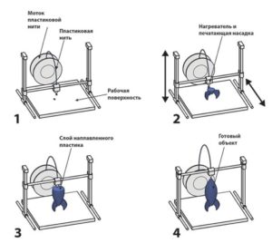
Figure 19 - Formation of an object using FDM 3D printing technology
Consider the main modes of 3D printing: temperature, speed, layer thickness, printer software settings.
In the operation of a 3D printer, it becomes necessary to adjust different temperatures. One of the indicators is the temperature of the first layer. The first layer is one of the most crucial moments in 3D printing of a product, since the further printing of the part largely depends on how well, evenly and in compliance with the necessary geometry the plastic will be placed on the 3D printer table. As a rule, the temperature of the first layer does not differ significantly from the temperature of extrusion and fluctuates within the limits of 0-10 degrees higher than the last one. The extrusion temperature is selected according to the material used. The recommended printing temperature is indicated on the resin packaging. It is important to adhere to the manufacturer's specifications to avoid 3D printing defects caused by incorrectly selected temperatures. Such defects include insufficient extrusion or overheating of the plastic. The optimum extrusion temperature depends on the type of polymer used. For a number of the most common materials and FDM printers, the recommended extruder temperature ranges are 200-245 degrees Celsius. The third temperature parameter that affects the quality of 3D printing is the temperature of the 3D printer table. Similar to the harm caused by overheating of plastic, it is harmful and unnecessarily rapid cooling of the layers of the material. In order to avoid deformation of the model during the 3D printing process, the printer table is heated. The temperatures to which a 3D printer table is heated usually range from 50-110 degrees Celsius.
Layer thickness or layer height is a pre-selected parameter in the software to prepare models for 3D printing. From a tactile point of view, the layer height determines how smooth the part is to the touch. But layer thickness can affect many properties of the printed product, including the strength of the polymer material. The phenomenon of change in strength occurs due to a change in interlayer adhesion when choosing a layer height. As a rule, the layer thickness of modern FDM printers varies in the range of 0,02-1,2 mm. Figures 20 and 21 show different layer thicknesses.

Figure 20 - Layer thickness at values of 0,2 mm, 0,4 mm, 0,6 mm (from left to right)

Figure 21 - Dependence of the accuracy of the side hole on the selected layer height
Nozzle diameter - The diameter of the smallest hole in a 3D printer nozzle through which a consumable is extruded. The choice of this parameter determines how accurately the 3D printer will enter the corners of the model and how well the relief of the part will be drawn. However, it should be understood that if the nozzle is very thin, then the risk of clogging increases and the time of 3D printing increases, since a smaller amount of consumable can be pushed through a thin nozzle than through a thick one. In addition to this, it should be noted that the larger the nozzle diameter, the higher the selection range for another important parameter, such as the "layer height". Therefore, the choice of this parameter is very important, it requires constant selection, monitoring and adjustment.
Nozzle temperature - the temperature to which the nozzle is heated in order to be able to extrude the thermoplastic in other selected modes (print speed, feed speed, retraction speed, retraction value)
Feed Ratio - A factor that adjusts the feed of the consumable to maximize the width of the actual extrusion. In the process of 3D printing using FDM technology, there is a regularity of volume preservation. The plastic does not burn, does not evaporate, but in the same amount that got into the nozzle, it is extruded. However, in some cases, the machine begins to “under-crush” or “crush”. Such cases are called "under-extrusion" or "over-extrusion". There can be many reasons for this: partial clogging of the nozzle, incorrect calibration of stepper motors, etc. For the 3D printer to work properly, this parameter must be calibrated. During printing, you can adjust this parameter to achieve any specific requirements.
Airflow is a parameter characterizing the intensity of the fan directed to the extrusion zone. During 3D printing, the extruded plastic must harden, the faster the better, because the layer will not have time to "float away" anywhere. However, for some materials, large airflow is dangerous, because it will cool the material excessively and delamination of layers or detachment of the part from the platform may occur. The parameter is set depending on the consumable.
Table Temperature - The temperature to which the 3D printer platform heats up during 3D printing. It is necessary for better adhesion of the first layer, the work of a special adhesive applied to the platform. Helps to heat and maintain the temperature in the 3D printer chamber.
Retract - rollback of plastic when moving the extruder without feeding material, for example, to a new perimeter. If you turn off this function, then when moving the material will begin to flow out and pull the thread with it, which will entail negative consequences in terms of quality. Two parameters are responsible for the retraction: the rollback speed and the rollback amount. If these parameters are incorrectly set, the plastic may simply be chopped or poured out of the nozzle. Adjusts depending on the material and the speed of movement of the extruder.
Infill - the density of the interior space of your part when 6D printed. The ratio of the filled space to the entire internal volume of the part [3]. The principle of Infill in 22D printing is clearly shown in Figure XNUMX.
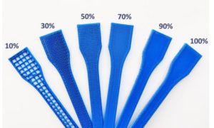
Figure 22 - Different percentage of Infill with the same wall thickness
Print speed - the speed at which the extruder moves while extruding the plastic. An equally important parameter to ensure the quality of the printed model is the print speed. An illustrative example of the influence of print speed on the quality of a manufactured object can be seen in Figure 23.

Figure 23 - Influence of 3D printing speed on surface quality
The illustration shows that an excessively high 3D printing speed makes the surface unusable (40 mm / s and 50 mm / s), while a printing speed that is too low does not provide the required performance. At low print speeds, the quality is acceptable, but this can negatively affect intercoat adhesion (the lower layers will cool down until the extruder reaches the loop again). The optimal speed according to Figure 1 for a given layer height is 30 mm / s. It should be noted that these optimum print speeds are only suitable for a certain material layer thickness.
Travel speed - the speed of movement of the extruder at the moment when the material supply is turned off, for example, when rolling to a new perimeter. It is set additionally with movement acceleration. The sharper the beginning of the movement, the better this fact will affect the breakage of the thread of the flowing thermoplastic. However, a very abrupt start can lead to displacement of the belt, which ensures the movement of the extruder. This parameter can greatly speed up the 3D printing process, but you need to accurately understand the capabilities and condition of the machine in order to work with this parameter at the maximum.
Lowering the table when moving - it is necessary so that the extruder does not touch the printed part of the object when moving.
The trajectory is programmed in special software, where all of the above and additional printing parameters are set. Figure 24 shows an example of applying material along different paths.

Figure 24 - Applying layers of material along different paths
2.2 Influence of 3D printing modes on the strength characteristics of ABS plastic. Finding optimal values
The material obtained by FDM printing can have a different structure, but it will necessarily consist of a set of volumes with unidirectionally laid threads. This is determined by the technological features of the implementation of FDM printing. Therefore, in order to determine the strength properties of the material obtained by FDM-printing, it is necessary, first of all, to investigate the strength of the model material with unidirectionally laid threads. In order to assess the strength characteristics of the material and the anisotropy of properties, tests must be carried out along and across the direction of laying the threads, as well as to test the threads themselves for comparison with the manufacturer's data [7].
To test the filaments obtained by extrusion through the nozzle of the extruder of a 3D printer, a 1,75 mm acrylonitrile butadiene styrene (ABS) filament PA-707 from the Taiwanese company POLYLAC CHI MEI CORPORATION was used as a starting material. For the extrusion of the experimental filament, the same coil was used as for the manufacture of samples of the model material [8]. The filament was extruded through a working nozzle of a 3D printer with a diameter of 0,4 mm. The loading rate of the samples was 10 mm / min. Figure 25 shows a sketch of samples for testing extruded filaments.

Figure 25 - View of a sample for testing extruded filaments
The diagram of the loading of the extruded thread has the following form (Figure 26), similar to the diagram of the loading of the samples along the laying of the threads.

Figure 26 - Diagram of loading of extruded filament samples
The test results showed that the average strength of the extruded thread (47,8 MPa) is close to the passport data for the material (48,8 MPa), but the values for the strength of the thread have a wide scatter - from 38,8 to 90,5 MPa (Table 1) ... The average relative elongation of the threads at the yield point (27,5%) is close to the passport data for the material (20%). However, a number of filaments break down almost brittle, while in others the relative elongation approaches 100%. The spread in the strength and deformation characteristics of the extruded filaments can lead to the spread in the strength of the material formed by the FDM-printing.
Table 1 - Results of testing filaments obtained by extrusion through the nozzle of the working head of a 3D printer
| number p / p |
d0 | d* | S0 | S* | РMax | Р*p | σ*p | σHR | l* | Δl | ε |
| /mm/ | /mm/ | /mm2/ | /mm2/ | / N / | / N / | [MPa] | [MPa] | /mm/ | /mm/ | /% / | |
| 1 | 0,46 | 0,46 | 0,166 | 0,166 | 6,909 | 6,37 | 38,33 | 41,57 | 15,9 | 0,9 | 6,00% |
| 2 | 0,47 | 0,29 | 0,173 | 0,066 | 7,889 | 5,98 | 90,53 | 45,47 | 29,2 | 14,2 | 94,67% |
| 3 | 0,46 | 0,44 | 0,166 | 0,152 | 6,811 | 5,98 | 39,33 | 40,98 | 18,5 | 3,5 | 23,33% |
| 4 | 0,45 | 0,44 | 0,159 | 0,152 | 6,703 | 6,17 | 40,58 | 42,15 | 16,9 | 1,9 | 12,67% |
| 5 | 0,47 | 0,46 | 0,173 | 0,166 | 7,350 | 6,47 | 38,93 | 42,36 | 16,7 | 1,7 | 11,33% |
| 6 | 0,45 | 0,35 | 0,159 | 0,096 | 7,056 | 5,49 | 57,06 | 44,37 | 21,1 | 6,1 | 40,67% |
| 7 | 0,45 | 0,45 | 0,159 | 0,159 | 6,174 | 6,17 | 38,79 | 38,82 | 15,1 | 0,1 | 0,67% |
| 8 | 0,44 | 0,43 | 0,152 | 0,142 | 6,272 | 5,88 | 41,45 | 41,25 | 15,7 | 0,7 | 4,67% |
| 9 | 0,44 | 0,36 | 0,152 | 0,102 | 6,664 | 5,49 | 53,94 | 43,83 | 25,2 | 10,2 | 68,00% |
| 10 | 0,46 | 0,45 | 0,166 | 0,156 | 7,301 | 6,08 | 39,09 | 43,93 | 16,9 | 1,9 | 12,67% |
The shape and dimensions of the samples for tensile tests were taken in accordance with GOST 11262-2017 Plastics. Tensile test method. For research, a sample of the second type was selected (Figure 27) [9].
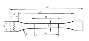
Figure 27 - Sketch of a tensile test specimen
The 3D model of the test specimens was created in CAD from Autodesk Inventor based on the drawing, then converted to .stl format suitable for 3D printing (Figure 28).

Figure 28 - 3D model of a sample for testing in accordance with GOST 11262-80 type 2
3D printing allows you to immediately produce samples for tensile strength tests, bypassing the stages of obtaining a primary blank and subsequent cutting of samples from it. The thread laying procedure (G-code) was prepared in the Simplify3D version 4.0 program in accordance with GOST 20999-83 “Numerical control devices for metalworking equipment. Coding of information of control programs "taking into account the location of the threads in the working part of the sample along or across the direction of stretching. Figures 29 and 30 show the difference in the position of the model on the table of the 3D printer.

Figure 29 - Screenshot of the Simplify3D program with the arrangement of threads in the working part of the sample across the direction of tension

Figure 30 - Screenshot of the Simplify3D program with the arrangement of threads in the working part of the sample along the direction of tension
3D printing was carried out using monofilament made of ABS + plastic manufactured by StreamPlast, supplied according to Technical Conditions - TU 2291-001-24687042-2016. In accordance with these specifications, the monofilament must have a tensile strength of at least 48 MPa and the printing must be carried out in the temperature range 220-2500FDM printing was carried out on a PicasoXPro 3D printer with an extruder nozzle diameter of 0,4 mm. Before printing, in order to improve the adhesion of the material, the table was covered with a special binder of The3D brand. The table temperature was 1100C, and the temperature of the extruder nozzle is 2400C.
Printing was carried out in three modes:
Mode 1: at the speed of the nozzle of the extruder Vс= 30 mm / s and the thickness of the laid thread layer hcl= 100 μm;
Mode 2: at the speed of the nozzle of the extruder Vс= 45 mm / s and the thickness of the laid thread layer hcl= 150 μm;
Mode 3: at the speed of the nozzle of the extruder Vс= 60 mm / s and the thickness of the laid thread layer hcl= 200 μm;
The obtained samples were tested for tensile strength at a speed of spreading the clamps of the testing machine corresponding to 1 ± 0,5 mm / s (the minimum speed of spreading the clamps of the testing machine, provided for by GOST 11262-80).
Experimental data on the results of testing the material obtained by FDM-printing using ABS plastic, along and across the laying of threads are shown in Figure 31.
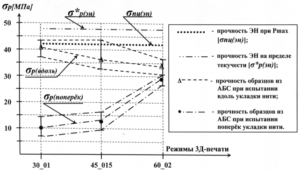
Figure 31 - Dependence of tensile strength σр of a model material with longitudinal and transverse laying of threads, obtained under different modes of 3D printing
From the presented data, it can be seen that the tensile strength of the material obtained by all three modes of 3D printing in the direction of laying the threads is close in its values and is at the level of 30-44 MPa. If we use the manufacturer's data on the strength of monofilament used in FDM printing (48,8 MPa), then these values are about 31% lower. However, for a more correct comparison of the strength levels of these two materials, it is necessary to clarify how the test conditions for monofilaments coincide with the conditions of their loading in the model material.
The strength of the model material across the filaments is significantly lower and depends more strongly on the FDM printing modes (Figure 31). The speed of the extruder nozzle in conjunction with the thickness of the applied layer affects the adhesion strength of the filaments [10]. This is due to the spread of heat from the nozzle into the material. At a high print speed, at any given time, less heat is transferred to the plastic at a particular point than at a low speed. If you print a small layer at a low speed, too much heat may be given off. This will increase adhesion, but there will be a risk of plastic sagging defects. Conversely, if you are 3D printing with a thicker layer at high speed, the heat may not be enough to form good adhesion between the filaments.
This assumption is confirmed by the obtained experimental data (Figure 31). In mode 1 (the minimum printing speed and the thickness of the laid layer), the strength of the model material across the laying of the threads is minimal and amounts to 7-15 MPa (72% of the strength of the material along the laying of the threads), in mode 2 - 10-16 MPa (66% of the strength material along the laying of the threads) and in mode 3 - 26-31 MPa (16% of the strength of the material along the laying of the threads).
Samples of the model material with longitudinal and transverse laying of threads have a different type of tension diagram and fracture surface (Figure 32).

Figure 32 - Types of tensile diagrams of samples with transverse (left) and longitudinal (right) laying of threads
If the tensile diagram of specimens with transverse filament packing has a characteristic form for brittle fracture, then in the tensile diagram of specimens with longitudinal filament packing, after a slight decrease in the tensile force, after reaching a maximum, its gradual decrease is observed until the moment of specimen failure.
Specimens with transverse fiber packing have an absolutely flat fracture surface (Figure 33), while specimens with longitudinal fiber packing (Figure 34) have a developed fracture surface.

Figure 33 - Surface of destruction across the laying of threads

Figure 34 - Surface of destruction along the laying of threads
When examining these kinks on an optical microscope, it can be seen that the destruction of the material with the transverse laying of the fibers occurs in one plane (Figure 35) along the surface of the laid threads. The fracture of the model material with the longitudinal laying of the fibers (Figure 36) has a developed character. Fracture proceeds in different planes, and both damage accumulation areas and flat zones characteristic of the main crack propagation are observed at the fracture.
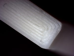
Figure 35 - Fracture of the sample with the transverse laying of the threads under the microscope

Figure 36 - Fracture of the sample with the longitudinal laying of the filaments under the microscope
2.3 Conclusion by chapter
Based on the data obtained, it is possible to draw intermediate conclusions about the strength of the model material obtained by FDM-printing using ABS plastic:
- the maximum values of the strength of the material of the samples when tested along the laying of threads are close to the strength of single threads obtained by extrusion of plastic from the working nozzle of a 3D printer;
- with an increase in the speed of the extruder nozzle and the thickness of the polymer layer being laid, the strength of the material of the samples when tested along the laying of the threads decreases by 16% (from 41 MPa to 34 MPa);
- the greatest variation in the strength properties of the material of the samples when tested along the laying of the threads is observed when the speed of the extruder nozzle is equal to 45 mm / sec and the thickness of the laid thread layer is equal to 150 microns;
- with an increase in the speed of the extruder nozzle and the thickness of the polymer layer being laid, the strength of the material of the samples when tested across the laying of the threads increases almost threefold (from 10 MPa to 29,6 MPa);
- samples of model material with longitudinal and transverse laying of threads have a different nature and type of fracture surface. The different types of diagrams of tension and fracture surfaces of specimens with transverse and longitudinal filaments indicate a difference in the mechanisms that take place in the material when it is loaded;
- with transverse laying, an absolutely flat surface of destruction is observed at the junction of the welded filaments, and, therefore, the amount of adhesion between them is the most important factor affecting the value of strength.
- in the case of longitudinal laying, the fracture of the material has a developed character both with areas of damage accumulation and with zones of the main propagation of cracks.
- a material with a longitudinal arrangement of threads in further studies should be considered as a bundle of connected fibers, which can reveal the mechanisms of destruction of such a material.
- Mode 3 turned out to be the most successful for us, since high printing speed allows us to achieve good productivity, while the strength is comparable to other printing modes.
3 Practical implementation of the research results obtained by the example of the manufacture of support rollers of a caterpillar propeller
3.1 Development of manufacturing technology for track support rollers from ABS plastic
Analyzing the previous chapters of this note, it can be understood that 3D printing has long been used in mechanical engineering for the manufacture of parts. We tested 3D printed samples. The result showed that such parts are comparable in strength to molded plastic parts. Summarizing the fact that it is possible to manufacture products of a limited range by 3D printing and the strength characteristics of the material obtained by the FDM printing method, it can be argued that 3D printing is suitable for the manufacture of mechanical engineering parts. To confirm or refute the theory, we took as a basis one of the real tasks - the design of a supporting roller for a caterpillar mechanism. Our task was to create a flow chart for manufacturing a supporting roller using additive processes with all their advantages. As the initial data, we were provided with an existing roller, which is made by alternative types of metal production. To implement this project, a large number of technological processes were investigated and a project implementation plan was drawn up: 3D scanning, reverse engineering, generative design, topology optimization, stress analysis and 3D printing.
3.2 Manufacturing of rollers supporting the tracked track
3.2.1 3D scanning
3D scanning is a method of obtaining data on the shape and dimensions of an object in spatial representation by recording the x, y and z coordinates of points on the object's surface and converting a set of points into an electronic geometric model using specialized software [12].
We used a RangeVision Spectrum scanner to create a 0,17D model and take the actual dimensions of the original video. With the roller dimensions, the measurement error was no more than 3 mm. Below is a point cloud captured by a 36D scanner (Figure 37) and a pre-processed model with stitched scans (Figure XNUMX).
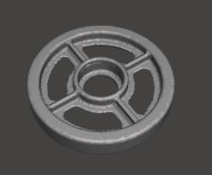
Figure 36 - Point cloud after 3D scanning

Figure 37 - Pre-stitched 3D model after 3D scanning
3.2.2 Reverse engineering
The reverse engineering process consists in sequential "wrapping" of a point cloud and a polygonal three-dimensional model with surfaces defined by formulas, as a result of which a solid 3D model appears.
For the reverse engineering process, we used AutoDeskInventor and Fusion360 software. Figures 38 and 39 below show screenshots of the program with the resulting 3D-model of the video.

Figure 38 - Result of reverse engineering

Figure 39 - Solid model of the roller in .stp format
Below is also a drawing of the original support roller based on the resulting 3D model (Figure 40).

Figure 40 - Drawing of the original video
3.2.3 Generative design
To reduce the mass of a part in the field of 3D printing, generative design is used - this is an approach to product design, which consists in making changes to a design or part, replacing a solid material with simple elements of any shape repeating in volume, in order to reduce the mass of a product, provided that the provided to him strength requirements [11].
The idea of generative design is to remove excess material under specific loading conditions, since 3D printing makes it possible to manufacture products of almost any shape. The use of 3D printing makes generative design feasible and possible, since it is only possible to obtain a given shape using this method.
The generative design was carried out using the AltairOptiStruct program, the operating conditions of the part were incorporated into the program.
Operating conditions of rollers:
| Track speed without slipping | 15 m / s |
| Roller load | 42 kg |
| Roller material |
ABS StreamPlast
|
The figures below show the variations in creating a generative product design (Figure 41)

Figure 41 - An example of generative design of various variations
For the reverse engineered 3D model of the support roller, a generative design was carried out with the aim of restructuring to reduce the mass of the roller. The result is shown in Figure 42, a section of the model obtained in automatic mode is shown in Figure 43.

Figure 42 - The result of the selection of the generative design of the supporting roller in automatic mode

Figure 43 - Section of a 3D-model of a roller of generative design
3.2.4 Optimization of surface topology and mesh structure
The program created a 3D model in accordance with the provided data, but later it turned out that the resulting model was not suitable for FDM printing due to its sub-optimal shape. Then the model after generative design is changed manually. Such changes are called topology optimization - this is a process in the design of products, which consists in making changes to a structure or part with the creation of new boundaries of the body volume and the removal of existing ones, in order to optimize it according to the criteria of minimizing mass, maximum stiffness and spectrum of natural frequencies, while maintaining the provided to him strength requirements. [11] An example of topology optimization is shown in Figure 44. As a rule, this happens in the AutoCAD Inventor CAD system: a specialist corrects the necessary parts of a 3D model and sends it for further processing.

Figure 44 - An example of topology optimization after generative design
The support roller was also subjected to manual topology optimization (Figure 45), and a drawing of the optimized model was obtained (Figure 46).
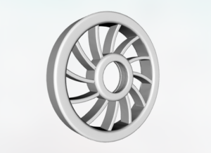
Figure 45 - Support roller after topology optimization

Figure 46 - Drawing of the video after optimization of the topology
Together with generative design, the preparation of the internal structure of the material is characteristic. The internal structure can be specified as honeycomb, lattice or special structure (Figure 47). Ansys Mechanical was used to define the internal structure of the voids of the support rollers.

Figure 47 - An example of mesh structures when optimizing topology
When forming a cellular structure, the program recommended using a wall thickness of 2 mm, and laying a cellular structure inside, convenient from the point of view of powder 3D printing, but not convenient for 3D printing using FDM technology. It was decided to form the structure of voids inside the part directly in the software for preparing a control program for a 3D printer with similar data obtained from the Ansys Mechanical program (Figure 48).

Figure 48 - Mesh structure defined manually in Simplify3D software
3.2.5 Stress Analysis
Based on the final 7,42D model, a stress analysis was performed in the AutoDeskInventor program. The analysis reports are presented in Appendix A, Appendix B, Appendix C, Appendix D. The program did not take into account vibrations, friction and temperature factors as the initial data, so a large safety factor was required to take into account all possible factors. By analyzing the data, we can see that the minimum instantaneous safety factor is 296. At the same time, the roller weighs XNUMX grams, which is almost two times less than if we printed the roller without optimizing the surface topology and did not use generative design technologies.
3.2.6 Production of a pilot batch
Having received the final model that meets all the criteria, you can prepare a control program for a 3D printer. Control programs can be either bundled with the 3D printer software or purchased separately for specifying print settings in more detail. In this case, the G-code was prepared in the Simplify3D program. Printing was done on PicasoDesignerXPro 3D printers. The nozzle diameter was 0.4 mm, the layer height was 0,2 mm, and the printing speed was 60 mm / sec. After 3D printing, the rollers (Figure 49) were installed and tested for a full 3 month service life. After successful tests, a batch of products was sold (Figure 50).
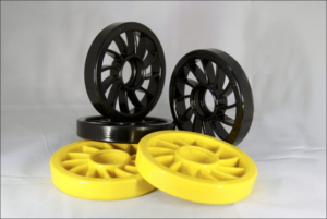
Figure 49 - Finished rollers for testing on machines

Figure 50 - Part of a batch of finished support rollers
3.3 Chapter Conclusions
A flow chart was created for the manufacture of a finished functional product by the method of additive manufacturing using FDM technology using generative design and topology optimization methods. In practice, the possibility of implementing the obtained research results has been tested on the example of manufacturing the supporting rollers of a caterpillar propeller. A pilot batch of rollers was made, intended for operation within the agreed period of 3 months.
CONCLUSION
Based on the above, we come to the conclusion that 3D printing is a technology that is widely applicable in various fields, including mechanical engineering. We made an assumption and showed the possibility of using FDM3D-printing technology for the manufacture of functional mechanical engineering products.
Studies of the strength of the model material formed by the 3D printing method were carried out and compared with the specifications provided by the manufacturers of consumables.
Applying the approach to hardening through generative design and topology optimization, we were able to significantly reduce the weight of the product, while maintaining the required mechanical characteristics under those loading conditions that were required in the customer's specification.
All the calculated data of the study in practice were confirmed.
LIST OF USED SOURCES
- Zlenko M.A., Popovich A.A., Mutylina I.N. Additive technologies in mechanical engineering. St. Petersburg: Polytechnic University Publishing House, 2013 p.
- Valetov V.A. Additive technologies (state and prospects). Tutorial. St. Petersburg: ITMO University, 2015 p.
- Shkuro A.E., Krivonogov P.S. 3D printing technologies and materials. Yekaterinburg: Ural. state forestry engineering. un-t. 2017 p.
- Sergeev A.N. 3D printers in medicine - field of application and prospects for the development of printing [Electronic resource] // Popular science journal. 2017 April. URL: https: //www.sciencedebatecom/25d-printery-v-meditsine-oblast-primeneniya-i-perspektivy-razvitiya-pechati/#3 (date accessed: 2)
- Kamonichkin D.T. 3D printing of surgical templates [Electronic resource] // Website of the additive manufacturing center. March 2018, 15 URL: https://studia3d.com/hirurgshablon/ (accessed 30.04.2019)
- Kamonichkin D.T. Percentage of Infill in 3D printing [Electronic resource] // Site of the center for additive manufacturing. 2017 February. URL: http://st04d.ru/3-zapolnenie/ (date of access: 5)
- Kamonichkina N.V., Kocheshkov I.V. Investigation of the strength characteristics of the model material obtained by the FDM-printing method // Additive technologies. No. 3. S. 39-43.
- Narisava I. Strength of polymer materials. M .: Chemistry. 400 s.
- GOST 11262-2017 (ISO 527-2: 2012) Plastics. Tensile test method
- Petrov V.M., Bespalchuk S.N., Yakovlev S.P. On the influence of structure on the strength of plastic products obtained by the 3D printing method // Bulletin of the State University of Marine and River Fleet named after Admiral S.O. Makarov. 2017. N 4.S. 765-776.
- GOST R 57911-2017 Products obtained by the method of additive technological processes. Terms and Definitions
- GOST R 57558-2017 / ISO / ASTM 52900: 2015 Additive manufacturing processes. Basic principles. Part 1. Terms and definitions


Author: Studia3D aggregator
More articles from Studia3D aggregator